The quality of the Timex/Sinclair 2068 video was never great: It was something some reviewers pointed out as observable on TV screens. Modern technology has only made that more obvious.
Problem One: Power
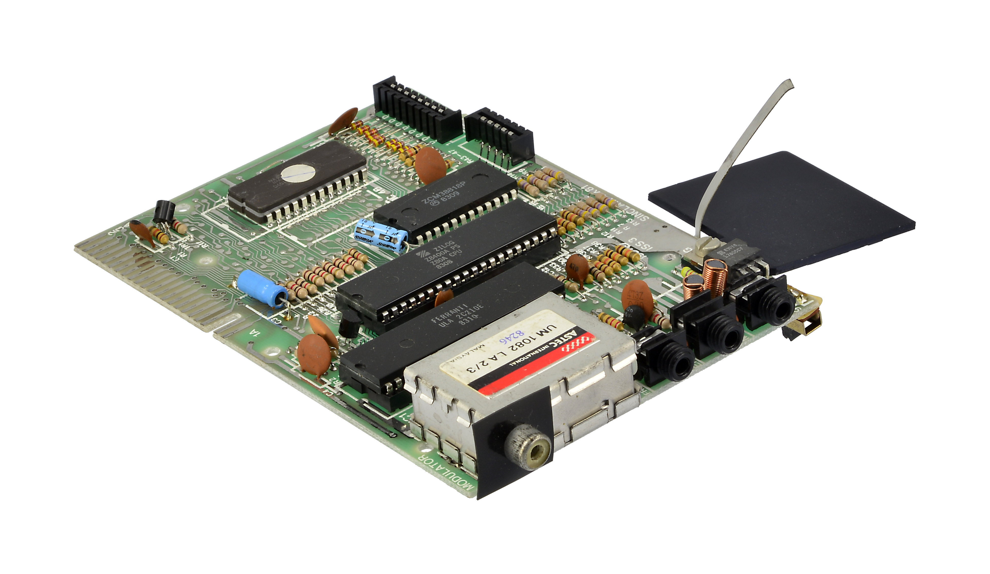
One of the major contributors to poor video signal quality is the computer’s power supply. The 2068 has two internal power supplies: a switching-regulated 5 volt source (uA78S40) and a 12 volt linear regulator (uA78L12).
Personal computers at the time had two kinds of power supply options: linear voltage regulators or switching power supplies.
Linear power supplies
Linear power supplies use devices like 7805 or 7812 voltage regulators to convert a higher voltage to a lower voltage. In general, the source voltage needs to be at least 3 volts higher than what you need. That’s why the power supply for the 2068 is 15 volts: it’s converted to 12 volts internally.
Linear voltage regulators have several issues a designer needs to content with: current limits and heat. The excess voltage is quite literally “burned off.” The ZX-81 and TS 1000 both use a 7805 to convert 9 volts to 5 volts. The difference is why there’s a metal heat sink in those computers.
The more power (current) the circuit draws from the regulator, the hotter it will run (the power difference also contributes to heat). If the heat sink is too small, the regulator will overheat and shut down. Before it does, however, it’ll provide less-than-optimal power.
A standard 7805 can deliver up to 1 amp of current, with an appropriate heat sink.
According to the manufacturer’s data sheets, the 78L12 in the 2068, “with adequate heat sinking, can deliver 100 mA output current.” There’s no heat sink on the 78L12.
Switching power supplies
The chip that makes up the main part of the 5 volt power supply can do a lot of interesting things, like convert a positive voltage to negative, lower voltage to higher and more.
Unlike a linear regulator, the switching regulator uses a combination of an oscillator, capacitors, resistors and a coil to do voltage conversion. The result is conversion without heat and no need for heat sink. In the 2068, it’s being used to convert 15 volts to 5 volts.
The quality of the power depends on the quality of the components. And, after nearly 40 years, some of those components have degraded. In particular, the capacitors are most susceptible because the electrolyte in the capacitors can dry out. And that can result in “noise” in the power supply.
What does power have to do with video?
A lot, actually. The chip (LM 1889) that converts the internal video signals to a signal suitable for a monitor requires 12 volts at about 35 mA. Remember, the 78L12 is supplying that. The 12 volts also supply the bias power for B-Y and R-Y vector inputs of the LM 1889.
It also needs a 5 volt chroma (color) reference signal.
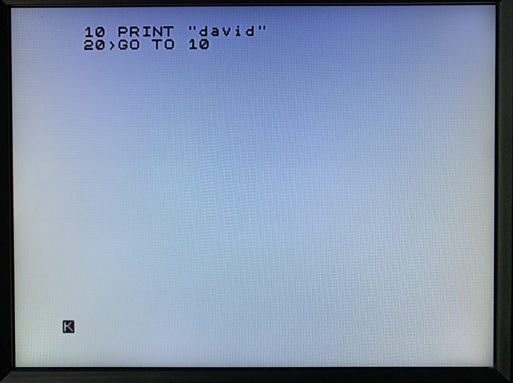
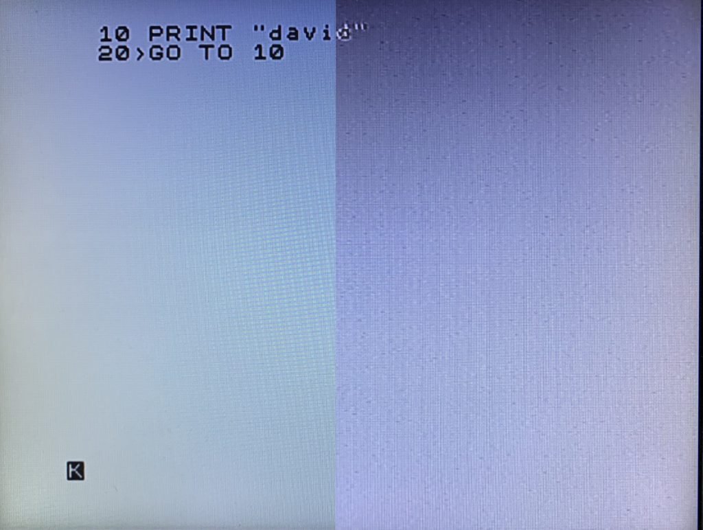
As designed, the 2068 was a little close to the limits and the result was clear in 1983. Even after passing through the video modulator in the computer and demodulator in the TV, users could see artifacts of poor power on their screen as ghosting and noise.
Add nearly 40 years to the circuit, along with modern displays, and it is really obvious.
How do you fix the power?
If you’re willing and adventurous, you can replace the power supplies in the 2068.
I’ve replaced the 78L12 with a 7812, which can provide more power without a heat sink.
I replaced the switching supply with a modern switching supply that is a drop-in replacement for 7805-based devices (like the ZX Spectrum). It can supply up to 1 amp and is the same device used in the Harlequin ZX Spectrum clone.
Replacing both involves removing a few parts, desoldering some and soldering in new parts and a few jumpers. It’s not impossible but it does require some prior experience.
Replacing those components will clear up about 80-90% of video problems, however.
Problem Two: Composite Video Sucks
Without going into a lot of ancient history, suffice it to say that composite video is a compromise that does not work well for a lot of computers. It is especially poor in the 2068.
Even the best composite signal will have ghosting and potential focus issues, largely as a result of how a signal originally designed to transmit black-and-white video was improved to carry color, too.
Like I said above, improving the power in the 2068 will address 80-90% of composite video signal problems in the 2068.
Solution One: Make a New Composite Signal
The Harlequin ZX Spectrum clone uses a special chip from Analog Devices (AD724) to convert video signals (red, green and blue) meant for special color monitors to a composite video signals.
It does this by using parts (synchronization) of the existing composite video signal. And that is why even this method results in a compromise. If you’re using an older composite monitor (like a Commodore 1702), this will work well.
Solution Two: Jump to HDMI
The same signals that can be used to make a new composite video signal can be used with a modern converter to make an HDMI signal, suitable for a modern display.
This, if you want a completely external solution, is the way to go. The video quality is fantastic.
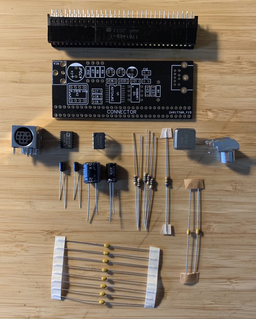
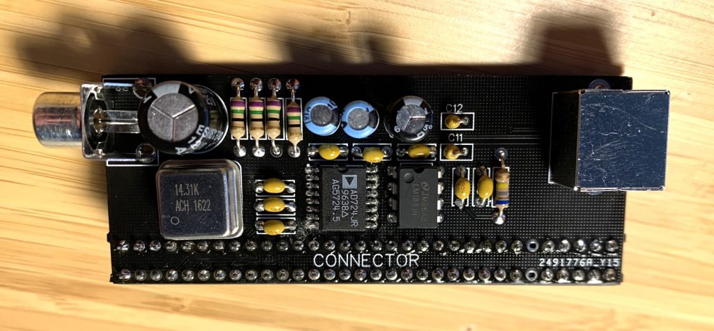
The 2068 Video Converter
You’ll need:
- a converter printed circuit board
- AD724JRZ
- LM1881
- 9-pin mini-DIN connector (Digikey: MDJ-009-FS)
- RCA jack (Digikey: RCJ-014)
- 470uf 25v electrolytic capacitor (Digikey: ESK477M025AH1EA)
- 220uf 25v electrolytic capacitor (Digikey: ESH227M010AE3AA)
- two 10uf 16v electrolytic capacitors (Digikey: UMP1C100MDD1TP)
- four 75 ohm resistors (Digikey: CF14JT75R0)
- one 680K ohm resistor (Digikey: CF14JT680K)
- two 0.01uf ceramic capacitors (Digikey: K103K15X7RF5TL2)
- eight 0.1uf ceramic capacitors (Digikey: K104K15X7RF5TH5)
- 14.31818MHZ crystal oscillator (Digikey: MXO45HS-3C-14M318180)
- 64-pin card-edge connector (Digikey: 1761469-1)
- a soldering iron (18 watts or more)
- solder
- solder-wick
- a Sega Genesis HDMI video converter with 9-pin mini-DIN connector
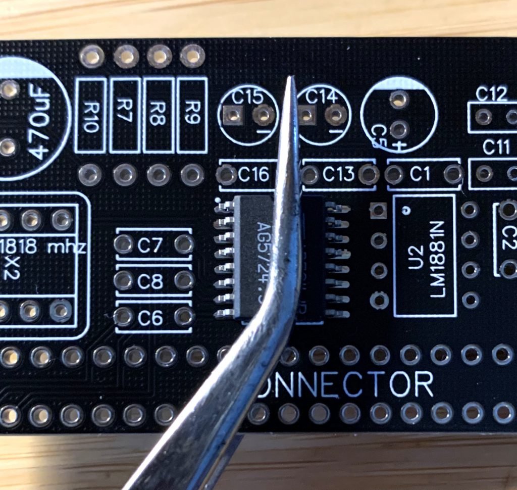
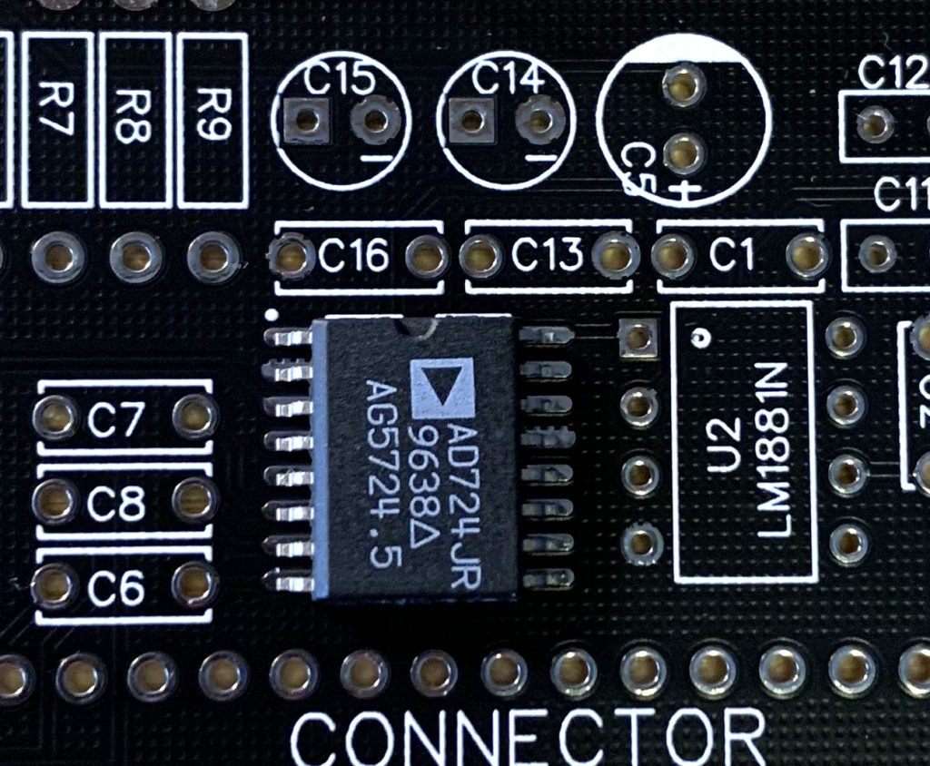
Solder the AD724JRZ
The most difficult part (for me, at least) is the AD724JRZ. I use clamping tweezers to hold the chip to the board; they’re strong enough to hold it firmly in place. The white dot and notch indicate the proper orientation of the chip. Pin 1 should be in the upper left.
Once positioned, look very closely and you’ll notice the tweezer tilts the chip slightly, so one side of the chip is lifted off the board slightly. I solder the two pins at the opposite end, then turn the tweezer around to compress the other side down. Once all four corners are soldered, you can take the tweezer off and solder the middle pins.
Once the middle pins are soldered, heat the end pins to release the tension.
You may notice that you bridged two or more pins with solder. Use your solder-wick to remove those bridges and excess solder from pins.
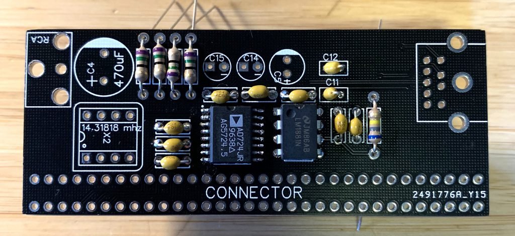
Solder the other parts in any order
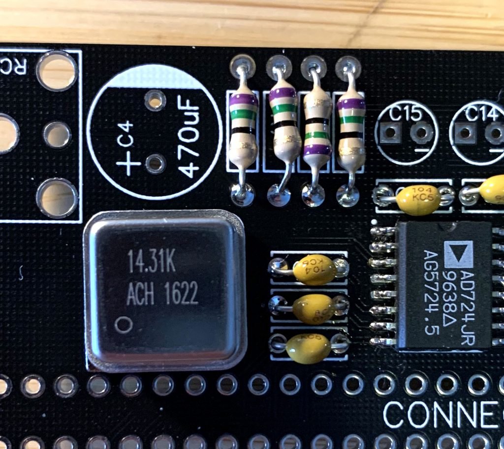
I usually solder the 75 ohm resistors (purple, green, black and gold bands; R7, R8, R9, R10). Resistors don’t have orientation. You can see that one of mine is not in the same orientation as the others.
The 680K (blue, grey, yellow gold) resistor goes in the R1 spot.
The two 0.01uf ceramic capacitors (marked 103) go in C11 and C12. Ceramic capacitors don’t have orientation, either, so it does not matter how you put them in.
The rest of the ceramic capacitors (marked 104) go in C1, C2, C3, C6, C7, C8, C13, C16.
Solder the LM1881 in U2. Pin 1 of the chip goes to the top left.
The electrolytic capacitors (C4, C5, C14, C15) do have an orientation: one pin is positive and the other negative. The long wire on the capacitor is positive. The capacitor also has a white stripe on the negative side, usually with a minus sign. The board is clearly marked for the capacitor orientation.
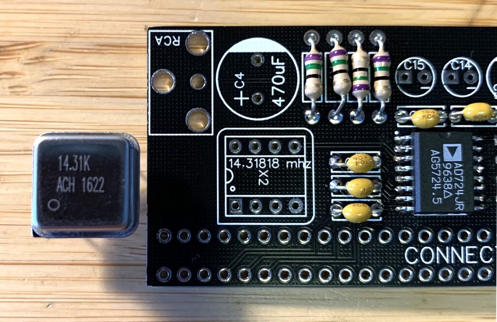
Solder the crystal oscillator
The crystal oscillator does have an orientation: a sharp corner indicates pin 1. The board has n outline that is the same.
Solder the video connector sockets
This is where you’ll need the higher power soldering iron. Insert and solder the RCA and 9-pin mini-DIN jacks. They go on the same side of the circuit board as the components. Solder both the signal pins and the tabs in their holes.
Prepare and solder the card edge connector
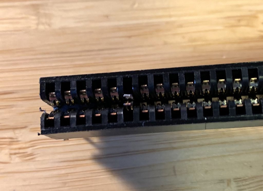
The 2068 needs a 64-pin card edge connector with some special preparation. First, almost all card edge connectors are closed, meaning they are meant to accept a card that’s no wider than the socket.
The ZX-81, TS 1000 and 2068 all require an open end card edge connector. Cut the ends off with a hacksaw, coping saw or whatever you have that can make a reasonably precise cut.
Next, count five spaces in. The next (the sixth) needs to be turned in to a “key” that fits in the slot on the 2068. There are two ways to do this: solder the fingers together or pull them and glue a shim in place.
If you’re going to solder the two fingers, use a small pick or tool to pull them closer together, heat the fingers up with your iron and solder them together.
If you want to use a shim, you’ll need to pull the fingers out with needle-nose pliers and cut a piece of printed circuit board down to about .25” square. I use superglue to hold my shim in place.
Last, when you insert the connector, it goes on the non-component side of the board. The components will face away from the computer when it’s mounted. The soldered finger/shim should be on the left when looking at the connector.
Stuff the connector in as far as it’ll go and solder just one corner pin. Make sure it’s flush with the board at all four corners then solder another pin. Solder the remaining corners and then all pins.
Test it out
Plug the connector on to the back of your 2068 (with the power turned off).
Connect your RCA video cable to the monitor out of the 2068. Turn on the 2068.
If you don’t get a video signal, turn your computer off right away. Remove the converter and test the monitor output of the 2068 again. Double-check all your solder joints and orientation of parts (especially the ICs, electrolytic capacitor and crystal). Also confirm that your shim/soldered fingers in the connector are at space 6.
If you do get video signal, try your RCA video cable on the output of the converter. It should be better than the native monitor output from the 2068.
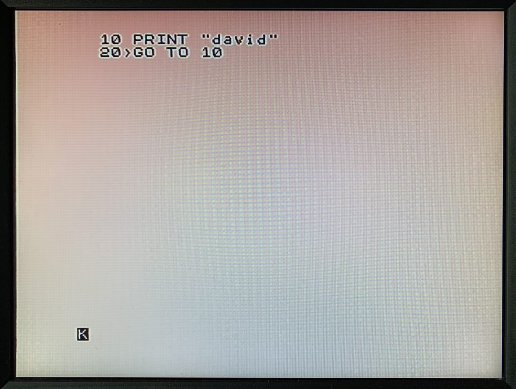
If you have the HDMI converter, connect and test it as well. It will provide the best video quality. You might never go back.