Authors
Publication
Publication Details
Volume: 5 Issue: 1
Date
Pages
Have you ever wanted to have some REAL pictures for your 2068? 1 don’t mean your usual pictures from your typical drawing programs but real pictures, such as your face, for example. This tutorial will show you how to hook up a video camera to your 2068 with a fairly simple hardware attachment.
I chose to wire-wrap my prototype and it worked fine but be sure to keep wires as short as possible in the op-amp section of the circuit. My version lives in the cartridge port but it would be easy enough to transfer to the rear connector if desired. Other than that I will leave the actual construction up to you.
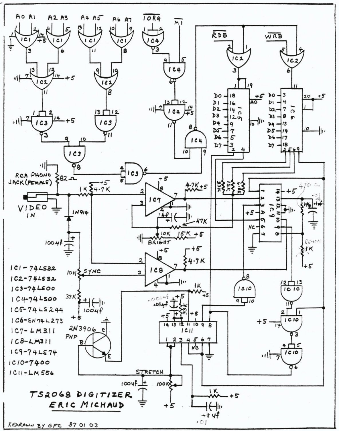
The circuit can be divided into two parts. The interface and the digitizing circuitry. The interface section simply provides 8 inputs and 8 outputs. Only 4 outputs are actually used along with 2 inputs. The extra lines could be used for your own projects.
I chose to map the interface to I0 port 00 but this could easily be changed to another port if it interferes with another piece of hardware. Small software changes would have to be made to accommodate for this change.
The digitizing section of the circuit essentially separates the video sync signal and the actual picture data from your video source and, by use of the LM311s, the picture is converted to a digital format. Then, through timing accomplished by the 74LS74N and the LM556, the picture is sampled at appropriate times to collect the image.
It is important to note that you must have a still video source as it takes 5 seconds to collect one image. Also, your video source must be capable of driving a monitor. RF video such as from a ZX81 will NOT work. A VCR or video camera with a MONITOR OUT jack will work.
For testing purposes, I recommend another computer with a monitor output plug or a VCR with shake-free freeze frame.
There are three controls on the digitizer. The BRIGHTNESS knob sets the brightness of the image. The STRETCH knob allows you to horizontally expand or compress the image. Finally the SYNC knob is used to place yourself ‘in sync’ with the incoming video source.
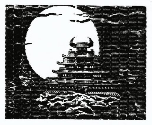
I will leave you with the schematic for now and in the next article, setup, theory and use will be discussed. In the meantime, I suggest that you obtain the driver software from the club library. The program is called EyByNi.B1. If you still aren’t convinced of the usefulness of this project, check out the picture I have taken from KARATEKA, an Apple II+ game.