
This is the final episode of a tutorial “mini-series” on the use of SRAM HI*RES EXTENDED BASIC (SHR-EB). This time around, we’ll wrap up our coverage of UDG’s (User-Defined Graphics), and examine some of SHR-EB’s truly unique aspects: Sprites, window-scrolls (“pseudo-sprites”), and the F-SAVE tape routines.
WHAT A DEAL!
First, though, we’d like to make you an “offer you can’t refuse.” Mr. Gregory C. Harder, main author of the SHR-EB, has developed a machine-code RLE (run-length encoding) decoder for use in conjunction with SHR-EB. What’s more, he has written it up in a wonderful tutorial article and has given it into public domain. All he asks is that you supply a 6×9″ or 9×12″ envelope and $2 for photocopying and postage. I’ll honor the same deal through Silicon Mountain. Send to Greg’s address as given in the SHR-EB documentation, or to Silicon Mountain Computers.
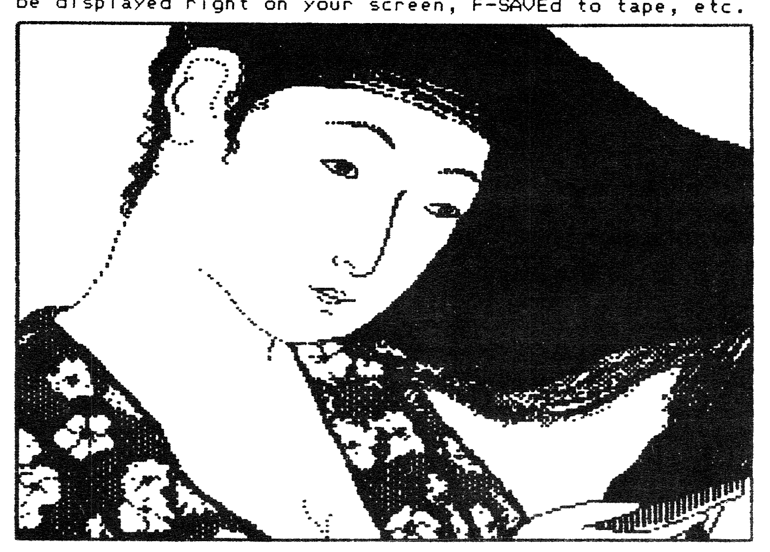
So what is “RLE” anyway? Essentially, it is a “standard” of data transmission of graphics and pictures. Data encoded in this way is thus transportable to any machine capable of at least 256×192 pixel resolution (as your T/S using SHR-EB), regardless of what machine was used to create the picture. Compuserve and several BBS services have RLE pictures on file, that you can download and decode using Greg’s routines. Would you believe the “Japanese Girl” picture originally used to promote MacPaint, on your humble TS1000? Believe it! This an many others (some of them very striking) can now be displayed right on your screen, F-SAVEd to tape, etc.
MORE UDG’S, PLEASE
In the BLACKJACK program, we create the pictures of the cards entirely using UDG’s. If you tackle such a project yourself, you’ll soon realize that this approach can easily “eat up” more than the 128 UDG characters available in the “MODE 2” UDG buffer. Don’t despair! There are ways of getting almost unlimited numbers of UDG’s.
The most obvious approach is to define new UDG’s, as required, “on the fly.” Redefining a UDG or set of UDG’s does NOT change what is already on the screen; after printing something using one set of UDG’s, simply redefine some or all of your UDG’s (perhaps by placing the definitions into a subroutine). In principle, you could fill the whole screen with different UDG characters (768 unique characters) using six different sets of definitions (6*128=768).
However, the amount of memory that would be used by all these definitions, even using the compact hex format, make this approach somewhat impractical. In the case of the BLACKJACK program, I found that I had the following UDG requirements:
3 - 5*8 face cards=3*40 = 120
"Vegas Bob" = 8
Fill character (back of cards) = 1
4 suit symbols = 4
4 upside-down suit symbols = 4
13 card symbols (A,2,3 etc.) = 13
13 upside-down card symbols =13

TOTAL UDG's REQUIRED = 163
Note that just the face cards and “Vegas Bob” use up 128 UDG’s, the total number available. Where do we get the remaining 35 required UDG’s?
The first UDG-saving “trick” was to scan over the definitions of the face-cards, to find any duplicated definitions. Some of the UDG’s used more than once are the ones corresponding to P, Y, and inverse 6. This reduced the number of UDG’s needed by 9, allowing me to include the suit symbols (normal and inverted) and the back-of-card fill character. Now I only had to accomodate the 26 card numbers (13 normal, 13 inverted).
For the normal symbols I could have, of course, used the mode 0 or mode 1 print characters. However, I found that the aesthetics were improved by using characters only 5 pixels wide instead of 7 (these were actually “lifted” from the 40-column character set in ZX-TERM*80). So where did I find 26 more UDG’s?
The solution was to define 26 of the available 32 SPRITE definitions. This points out the first characteristic of a sprite; it is basically just a special UDG, and can be used analogously to a normal UDG. The differences are as follows:
1: Printing a sprite does not overwrite what is already there; instead, it “ORs” the image with what is on the screen at that location. TS2068 users will recognize this property as the OVER command. So, in a sense, we’ve added the OVER feature to the TS1000 with the inclusion of sprites in SHR-EB. If you’re using sprites merely as a UDG, you have to be sure that nothing is printed at the proposed sprite location. If in doubt, print a space first, then print the sprite at the same location. In the BLACKJACK program, this is not a problem, and is therefore un-necessary.
2: The screen is mapped differently for SPRITE PRINT than it is for normal or UDG PRINT. The reason will become clear when we explore the sprite commands in greater depth. For now, simply remember that the vertical axis is inverted, and the horizontal axis is multiplied by 4. In other words, sprites use PLOT co-ordinates instead of PRINT co-ordinates. This will require a bit of juggling if you’re using a sprite as a UDG. A careful study of the PRINT CARD subroutine at lines 10-130 may give some insight into this.
The third UDG-saving trick occurred to me only after writing the BLACKJACK program. Had I thought of it earlier, the coding of the CARD PRINT routine might have been somewhat simpler. However, “I have written what I have written,” so I’ll simply describe the method for your use in your own programs.
There is no reason why the “mode 1” PRINT mode HAS to be lower-case characters. BLACKJACK does not use this PRINT mode at all, to save you the trouble of first loading a lower-case character set, like the one contained in HR*DEMO*1.
PRINT mode 1 redefines CHR$ 38-63 (A-Z) and CHR$ 128-165 (inv. space-inv. 9). Normally you’d use this for lower-case and custom characters, but there is no reason why you couldn’t use these to give you 64 additional UDGs. Printing the inverse alpha characters from mode 1 will still give (normal video) capitals, and the lower graphics and symbols will remain the same, but the rest will now give your additional UDGs.
Note that, in our documentation, we say that “There are no commands from BASIC to change these patterns.” In other words, there is no analog to LPRINT U; or LPRINT SD; for this mode. However, you CAN use BASIC (good old PEEK and POKE) to transport UDG definitions into the mode 1 buffer. Proceed as follows:
1: Define up to 64 UDG’s as usual. You will have to define them in two blocks: the first block runs from A to Z (CHR$ 38-63), and the second block from inverse space to inverse 9 (CHR$ 128-165). These will end up being the “alternate” (mode 1) set. Execute the definitions to store them in the UDG buffer.
2: Move the newly created characters from the UDG buffer (BUF1) into the mode 1 buffer (BUF2). The following routine will do the trick:
1000 FOR N=15360 TO 15663
1010 POKE N-512,PEEK N
1020 NEXT N
1030 FOR N=15664 TO 15871
1040 POKE N-1024,PEEK N
1050 NEXT N
(FAST mode recommended)
3: Define your “main” UDG set (up to 128 UDG’s) as usual.
Your alternate set will now be housed in the mode 1 buffer. Access these using PRINT;;; and access the main set using PRINT;;;; as usual. You now have 192 “true” UDG’s at your disposal, without having to resort to sprites. Note that when you re-LOAD your program later, you will have to re-execute the definition lines and PEEK/POKE loop before running the program, to insure that the alternate set as well as the main set of UDGs are stored in their respective buffers in your SCRAM or similar static RAM board. See also the section on F-SAVE MAGIC for time-saving short-cuts.
PHILOSOPHY CORNER
As a lead-in to our discussion of sprites, here’s a bit more “SRAM HI*RES philosophy.” In designing SHR-EB, we tried to make a package that is useful to the broadest range of users, maximizes flexibility, is immune to crashing because of user error, while maintaining at least some degree of standardization with BASICs for other systems. Quite a tall order; the result, we feel, satisfies all these criteria. However, some features may not be needed by all users, and some aspects may require some degree of compromise.
For instance, with the inclusion of a 64-column PRINT mode, we decided to double the range of the PRINT AT and TAB commands. To reduce confusion, the same horizontal range (0-63) is used for ALL printing modes. In other words, the horizontal co-ordinates are multiplied by two, as compared to the original Sinclair system. Similarly, since we can now start printing on any vertical line, the vertical PRINT AT co-ordinate is multiplied by eight. Still, we followed the Sinclair convention of placing the “origin” (PRINT AT 0,0) at the top left of the screen.
It is a Sinclair quirk that PRINT and PLOT use inverted vertical axes. In other words, the origin for PLOT is at the lower left corner of the screen. Furthermore, the axes are expanded since we can PLOT at twice the resolution of PRINT. When coming up with a high-res PLOT, we decided to retain the Sinclair protocol. After all, we wanted to write a true extension to Sinclair BASIC, rather than “dream up” our own version of how BASIC should operate. As a result, our PLOT co-ordinate system closely parallels that of the Spectrum/TS2068. The only real difference is that we have two screen-size modes (22 and 24 lines). In 22-line mode (IF USR HR THEN CLEAR), the co-ordinates are just like the Spectrum/2068. In 24-line mode (IF USR HR THEN RUN), the origin is moved downward by 16 pixels, giving us a range of 0-191 instead of 0-175.
So we basically have two discrete systems for defining screen locations. The first goes from 0-63 horizontally, and 0-191 vertically starting at the top (PRINT and related commands like LPRINT U;). The other goes from 0-255 horizontally, and 0-191 vertically starting at the bottom (PLOT, DRAW, WINDOW and similar commands). Which system is used depends on the range of the particular command. The only real exception is the REVERSE command (IF USR HR THEN RAND). Since we can only control 32 columns of screen locations for video reversal, and cannot control the effect vertically, the range for this command is only 0-31 horizontally.
THE AMAZING SPRITE
Sprites are mapped like PLOT, starting at the lower left. The reason is that sprites (unlike UDGs) can be placed at ANY horizontal pixel location. Another reason is that SPRITE MOVE shares the same line-drawing algorithm used by DRAW.
The sprite commands are: SD; (sprite define), SP; (sprite PRINT), SE; (sprite erase), and SM; (sprite move). These are all Group 2 commands, so must of course be preceded by IF USR HR THEN LPRINT. Like the other Group 2 commands, they can be concatenated into multiple-statement lines. Without getting into depth on the syntax requirements (read the manual!), here is how you use these commands.
Sprite Define (SD;) is used almost precisely like UDG Define (U;). The only difference is that with UDGs you define the starting character as a string literal (in quotes), whereas sprites do not relate (“correspond”) to character sets, and are therefore defined using a numerical sprite number (0-31). The hex sequence that follows the starting sprite number defines the pattern(s) for the sprites (up to 32). As with UDGs, you can get the apparency of a lot more than just 32 sprites by judiciously redefining sprites “on the fly.”
Sprite Print (SP;) puts a specified sprite at the specified location on the screen. You are in effect “plotting” the sprite, since as pointed out before, the SP; command uses the PLOT co-ordinate system. The location specified relates to the upper left corner of the sprite pattern.
When using sprites simply as “extended UDGs” as in the BLACKJACK program, these are the only two commands you’ll be using. The other two are used when employing sprites for their intended purpose – movable “transparancies.” Until now, things you put on the screen were immutable and permanent. In a sense, sprites are “above it all.” As mentioned, when printing a sprite, it does not erase what is already there. Instead, it is as if the white portions of the sprite are transparent, allowing what is “below” to show through. Similarly, when removing or moving a sprite, only the sprite pattern is affected; what was there before is left alone.
This is where the Sprite Erase (SE;) command comes into play. This removes the last sprite printed or moved. If you don’t invoke SE; before printing or moving the next sprite, the previous sprite becomes a permanent part of the “background plane” or main screen display. You can therefore selectively allow sprites to “melt” into the background, or vanish without a trace.
Sprite Move (SM;) moves a specified sprite around the screen in a specified straight line. Anyone who has viewed the HR*DEMO*2 program supplied with the SHR-EB package needs no convincing as to how impressive this can be. As with Sprite Print you must follow Sprite Move with Sprite Erase to prevent it from “solidifying” into your background.
PSEUDO-SPRITES
The biggest limitation with the SHR-EB sprite commands is that they only operate on single 8×8 pixel patterns. What if you want to move larger figures around, a pixel at a time?
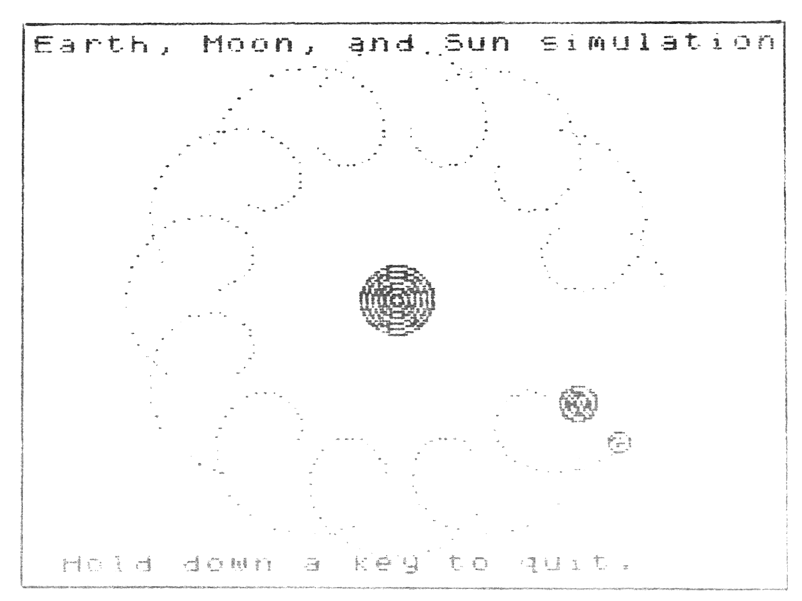
The bad news is that true “big sprites” are not possible using SHR-EB. However, you can obtain “pseudo-sprites” using the window-scroll commands (WU; WD; WL; and WR;). Study the “Earth-Moon-Sun” part of the demo to see an example of this. The moon is a true sprite; notice that it does not erase its orbital path as it crosses it. The Earth, on the other hand, is a pseudo-sprite. Like a true sprite, it moves around a pixel at a time. However, since it’s in the background plane it erases things that it crosses, as the moon’s orbital path.
The one advantage of the pseudo-sprite over the true sprite is that it requires no additional definitions. No matter how you create the pattern to be moved, it will move as a unit when using the window commands. As a point in fact, the “earth” figure in the demo was created using a combination of CIRCLE (multiple use of PLOT) and SPRITE PRINT (the moon was printed twice, one pixel apart, at the center of the earth, to give it that textured look).
You may have to experiment with the exact size of the window to be moved, depending on how far you are moving it, to prevent stray pixels from being left after the move.
F-SAVE MAGIC
What does F-SAVE stand for? I’ll leave it up to your imagination. It’s a Fast tape routine written by Fred, and I have since given the central algorithms away for Free to others for inclusion in their Fine software. If you’re having trouble with F-SAVE, you might come up with other meanings.
However, if you ARE having trouble, don’t despair. If it seems to ALMOST work, it usually will only require an inverted load cable to work on your particular system. See the second paragraph on page 18 of the documentation.
Assuming that you’ve gotten it to work properly, though, I’ll discuss some nifty features of the F-SAVE package that you may not have thought about. The first of these is the usefulness of the BOOT program included in the package. This is a shortened version of the F-SAVE “Load” command only. Save a copy of this as the first thing on each of your SHR-EB F-SAVE tapes. On power-up, you can thus load BOOT (takes only about a minute), then immedatiately fast-load your applications programs.
When you load BOOT, it stores a duplicate of the F-SAVE load routines at the usual run-time location, then proceeds to actually run it. As your application program loads, it of course will “overwrite” the copy installed by BOOT. However, since it’s an exact copy, the load routine just keeps running!
Once the first SHR-EB application has been loaded, the F-SAVE routines will of course be present in memory, and you can use it to load other programs, variables, or screen data.
The second point relates specifically to the BLACKJACK program. Refer to lines 9100-9150. After loading the program conventionally, you can GOTO 9100 to F-SAVE the program to tape. The first thing that happens is that we POKE location 32600 with a “1”. (Why? We’ll see later.) The BLACKJACK program is then saved by the command IF USR HR THEN SAVE “BLACKJACK”,P in line 9120.
Next, since location 32600 contains a “1”, the program saves the entire contents of the 8-16K region, including the current screen, all UDG and sprite buffers, and system variables. The line that follows (9140) is ignored, since location 32600 contains “1”.
Since we’re saving (and later reloading) the entire 8-16K region of memory, we have no need to redefine all those sprites and UDGs! This means that you can BREAK operation at the cover screen, return to the normal screen display by entering FAST mode, and then delete all lines from 9000-9021. The memory you save thereby can be used to install your own additions and refinements. Then GOTO 9100 to F-SAVE.
Let’s analyze what happens when you later reload the program. This will normally be right after power-up or NEW, so location 32600 will contain a “0”. This location is right near the top of your 16K memory, specifically 168 bytes below the default RAMTOP. This is just low enough to be out of the way of the stacks (under normal conditions) while being well above the end of the BLACKJACK program. After program loading has completed, the program will auto-run starting at line 9130. Since location 32600 is beyond the end of the program, variables and workspace area (higher than STK_END), it will still contain “0”. Line 9130, which would otherwise try to F-SAVE the present (presumably trashed or otherwise not apropos) screen area, is therefore ignored. Instead, it fall through to line 9140, which WILL execute because 32600 does not contain a “1” This causes the DATA (screen and UDG/sprite buffers, etc.) to be loaded from tape. As mentioned before, the UDG and sprite definitions will already be in place, and there is no need to re-define them. The program therefore jumps directly to the cover-screen routine at line 2000.
Once again, SHR-EB manages to impart features to the TS1000 that are suspiciously reminiscent of the Spectrum/TS2068. While not quite as comprehensive as the Spectrum tape routines, F-SAVE does drastically improve the flexibility of the machine by offering various “import/export” options for screen data and/or BASIC variables.
Getting back to the topic of RLE graphics for a moment, here is one possible scenario for manipulating your screen images. After downloading an RLE picture from a BBS, using either ZX-TERM*80 or Mini-Xmodem, follow Greg Harder’s instructions for decoding and displaying the picture. The decoded picture can then be F-SAVEd to tape for future viewing. You could then load the “Thrust” variant of Sinc-Artist, and use its swap feature to transfer the picture into Sinc-Artist’s A$. You can now use Sinc-Artist to polish up the picture, add or delete features, etc. When done with your graphic manipulations, transfer it back into low memory. You have a full graphics system that compares favourably with MUCH more expensive systems which will remain MacNameless.
A FEW IDEAS
What can you do with SHR-EB? Well, you could start by designing your own “Classy Front Ends” as Paul Bingham did for the 2068. You could even use Paul’s character patterns as published in TDM 3:5. Since Paul published the patterns in decimal, you’ll have to convert to hex to use them in the SHR-EB “LPRINT U;” command. This is a great opportunity to use the easy dec-hex conversion technique given in Appendix II of the SHR-EB documentation.
Foreign character sets? No problem. Russian, Hebrew, Greek, and KataKana characters are now possible. By studying how the 64-column character set is arranged in the data table at 4E94-5093h you could even come up with foreign 64-column characters. (HINT: each nybble contains a character. Split each group of eight bytes into left and right nybbles.)
How about high-res “big characters?” You could use UDGs to design, let’s say, 2×3 Olde English characters. Use the techniques outlined in this article to economize UDGs, and you should be able to design custom characters for the whole alphabet. Use the string array approach as in BLACKJACK to store the UDG codes for each character, and print them out in a loop.
Need a transparent flashing cursor? A sprite would be a natural for such an application. What other applications can you dream up for the Sprite Print, Sprite Erase, and Sprite Move commands?
Machine-coders: Use short LDIR routines to shuffle around various sprite and UDG definition tables. This will give you fast graphic possibilities limited only by your imagination and available memory. Incidentally, the HR*CORE program contains Hot Z names for all the major routines and variables; many of the routines can be usefully called from within your machine-code application.
The possibilities for adaptation of Spectrum and 2068 software are endless. Over the years a great many programs have appeared, that would have looked silly in the old low-res system, but are now quite feasible. Many books of interesting routines exist for other computers, as IBM PC and Apple. These, too, are now “fair game” for your not-so-lowly-anymore ZX/TS.
Thus ends the SHR-EB “BLACKJACK” tutorial. Will I write future articles on the care and feeding of this remarkable BASIC extension? Well, it depends on you. If you found this series useful, let your Editor know! If you have specific questions, don’t hesitate to ask me or Greg (why do you suppose we publishsd our addresses?). If you have found interesting applications, short-cuts, hints or tips, take the time o write them up and send them in for publication. Now that we’ve kicked off the “cheap hi-res ball,” it’s up to you guys and gals to catch it and run with it. Enjoy the game!