For starters, would you please dig out your October 1986 issue of ZX-Appeal and read Wilf Rigter’s article on pg 9 entitled “Z Voice” ?
Thank you! Now I only have to talk about how to assemble the hardware. The schematic has been slightly expanded in detail over the one published in Oct ’86, but it is essentially the same. Please refer to “Notes for Experimenters” on the schematic for explanations of differences.
Please refer to the “Bill of Material” for your shopping/inventory list. If you are building the board for a TS1000 or ZX 81 only, cross C10, C11, RG, and X1 off your list. If you are building for a 2068, cross off J2.
- The 2068 version will work on TS/ZX 81
- Ken Abramson is adapting the software for the 2068 and it may be in time for this issue of ZX-Appeal or the next one for sure.
- You can not use this board on a Spectrum (pin 23 (Reset on ZX 81) is -12VDC on Spectrum)
Ken Abramson also advises that in areas near strong radio transmitters, speaker leads can act as an antenna: you end up listening to the station as well as Z Voice! The fix for that is an RF bypass capacitor .001 μF across U2 input pin 3 to ground.
I guess you have all your parts by now, and you are ready to populate the board. If you use an earphone jack (optional) you will have to enlarge the existing hole to the correct size to fit your particular jack. You could also solder in your speaker leads directly into the board and forget about an earphone jack.
If you are building the 2068 version, please read the “Notes on Installation of RG” on the component layout drawing before continuing.
Also, this is a good time to decide whether you wish to install the optional audio amp bypass for external audio amp connection and operation – please refer to the schematic.
WARNING: The wire wrap pin edge connector is inserted into the board from the solder side!
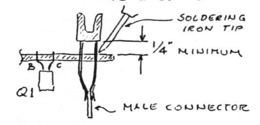
Be careful to avoid solder bridges between the pins – you can’t get “in there” to fix them!
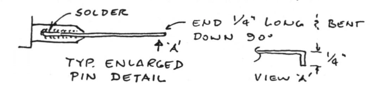
Solder the male connector between the pins, having observed the correct key slot position. One way of doing it is to align the male connector with and then solder it to the outer pins on both ends first, and then all the others.
Mounting the thumb wheel volume control as shown on the component layout has the advantage of being able to turn it easily with one’s fingers whilst trying to avoid “wabbelling” the RAM pack.

Attach bare 22 ga wire (solid) leads to volume control as shown. Refer to component layout for installation detail.
After soldering components into place, cut all protruding leads as flush as your IC socket pins (or IC pins if you skipped the sockets). Check everything very carefully: watch for solder bridges and “opens” in the traces. – O.K.? Plug it into your machine and watch for the ‘☒’ cursor to appear. If it does not within the usual time, “shut her down” and trouble-shoot the board.
Install your software as per the Oct. ’86 article and HAPPY ZX VOICING TO YOU!