Last month when I started my article for the printer interface, I came up with the idea of using the cartridge port. I had designed the printer interface using the rear edge connector on my ‘proto-board’ and everything worked great on that. As I was writing the article, I changed heading and actually altered the schematic without implementing the changes using the cartridge port.
Since then, I have built prototype and actually do use it (In fact, for this article). I cut an edge-card board down to size and mounted the components and had room to spare. The wire from the interface comes out where the door meets the bottom edge and bends around and out from underneath the computer. The cartridge door closes perfectly and there is plenty for room for the ribbon cable to exit underneath the computer.
Using the cartridge port seemed a logical idea with all the other peripherals I had hanging off the rear edge connector, little room was left for anything else. I started laying out the printed circuit board and realized (again) that another improvement was in order.
Why not add an EPROM holder to the board and have a combination printer interface/EPROM board? So I scrapped the layout I had almost finished and started laying out one that would hold the EPROM board schematic shown in the 2068 technical manual. This required a little more time and work and as of this writing, I’m not quite finished so I’ll have to wait till next issue to print my masterpiece.
Fortunately, all the signals needed were available from the cartridge port with the exception of RESET which is not absolutely needed but could be emulated using a “poor man’s reset” which is a resistor – capacitor combination which will bring the common line between the two to a low (loglc 0), simulating RESET.
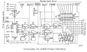
You will notice that last month, I connected the “poor man’s reset” directly to the INIT of the printer and to the R-S flip flop combination (74LS11(C), 74LS20(B), and 74LS02 (D)). This allows the printer to reset the interface, but when you turn on the computer, it’s possible to fill the printer’s buffer with nonsense characters because the INIT line floats high to logic 1 and won’t allow the computer to bring it low when it powers up.
This is really no big deal and can be cleared by simply sending something to be printed to the printer.
Hardware wise, there is a simple solution. Instead of going directly to the INIT line of the printer, go through one of the unused buffers of the 74LS367 – namely in on pin 10 and out to INIT from pin 9. This will isolate the INIT from the RESET until the computer is turned on which in turn turns on the buffer and resets the printer while RESET is still low.
Please note the correction in this month’s issue. Also, the missing pin numbers for the 74LS02(d) have been included.
I finished last month telling how the decoding of the ports work which allows emulating both the Aerco and Tasman interfaces. This finishes the operation with how the data is read from and written to the printer.
The first thing that must be done before data is sent to the printer is to check the status of the printer. The printer must be ready to accept data before any can be sent, otherwise, that data will be lost and only garbage will print. SELECT tells whether the printer is on line or not and PAPER tells you when the paper has run out on your printer. INIT clears the printer’s buffer and resets it. BUSY tells you when the printer is ready accept new data and STROBE is a signal to the telling it to load data into the buffer for printing. These ‘handshaking’ lines keep everything order so the proper operation happens at the proper time.
When the interface is powered it resets the flip flop into the read state. The printer line that must be checked is the BUSY line. Programs written for the Tasman interfaces check bit 0, those. written for the Aerco interface check bit 4. Notice on the schematic that the BUSY line goes through the 74LS367 buffer to both bit o and bit 4.
Once the program has determined that it can send data, an out command is done to the printer I/F port placing the printer data on the data buss lines of the computer. This out command ‘clocks’ the 74LS374 and ‘latches’ (stores) the data onto the printer data lines. This also toggles the flip ‘strobes’ flop and ‘strobes’ the printer, filling the printer’s buffer with data to be printed.
This process takes place each time a character is sent to the printer. when is happening, the 74LS367 and 74LS374 are in are their “tri-state’ which isolates the computer’s data buss so that it can perform other operations.
The EPROM part of the interface is basically the same as that shown in the 2068 technical manual in figure 5.1-1. This the same configuration as what Doug Dewey uses for his EMU-1 Spectrum Emulator, and what Ray Kingsley and John Oliger use for their EPROM cartridge boards. I used a ‘solder transition connector’ (like what Aerco uses) to permanently terminate the ribbon cable to the p.c. board and a standard crimp-on Centronics style ribbon connector on the other end. I have had no problem using this on my Panasonic printer, a Riteman, and the Star (Gemini 10x) printers.
Next month, I will talk about print routines to drive the printer interface and I promise to have the printed circult board layout.