This month I finish up my series on the printer interface with the circuit board layout and simple print driver software.
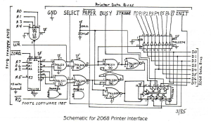
In reconfiguring the layout to include the ROM interface, I had to rearrange things a bit, so here is the final version of the schematic showing the new pin configuration. The schematic to the ROM interface is identical to what is shown in the 2068 technical manual.
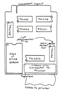
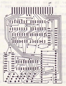
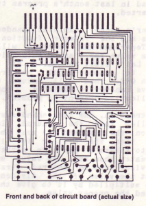
This takes a double-sided board which is very difficult to align properly, so take great care in transferring the layout to copper. It would be advisable to send it off and have it done professionally which is what I am having done.
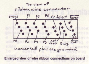
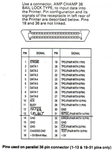
I used a standard centronics connector with 26 conductor ribbon cable to match up to the 26 pin solder transition connector on the interface board. Note that this only takes care of pins 1-13 and pins 19-31 on the printer connector. This is where all the necessary signals for proper operation are (see diagram) . Also note that all the signal pins (except INIT) are on the top side of the connector and that all the lower pins (19-30) are ground. This makes every other wire in the ribbon cable a ground which isolates all the data signals. That is why every other pin on the interface connector is a ground. When you make up the cable, make sure that pin 1 of the printer connector goes to pin 1 of the interface connector.
The signals shown and used are for my Panasonic KX-P1091. Your printer may be slightly different. The only signals absolutely required are STROBE, DATA 1-8, and BUSY. The other pins are just luxury (my schematic lists DATA 1-8 as PO-7) . In fact, All software that I have seen written for Timex and Sinclair use these signals.
To use the interface, plug the interface in, turn on the computer and load any program for use with Tasman or Aerco printer interfaces (with print driver software built in such as Tasword, Mscript, Textwritter, etc.) and enjoy! No more worries about POKEing this and that.
To use the interface with your own programs, the following program will take whatever is placed in a$ and print it. You can format a$ to print out in any mode you choose by checking with your printer manual and placing the proper codes in a$ around your text. Use it as a subroutine in your own program.
 9000 REM a$ contains material to be printed
 9010 FOR n=1 TO LEN a$
 9020 IF IN 127<>236 THEN GO TO 9020
 9030 OUT 123, CODE a$ (n)
 9040 NEXT n
 9050 OUT 123,10
 9060 RETURN
Line 9010 checks for the length of the string to be printed and sets this as the number of loops the program makes. Line 9020 checks to see if the printer is ready for data to be sent. My printer reports with 236 when its ready to receive data, yours may be different. To check yours, simply turn on the entire system and enter: PRINT IN 127 or 63 or 191, and this will give you the ready data. Use that if its different from mine. Once the printer is ready for data, line 9030 outputs to the printer the current ‘slice’ of a$. It then goes back and gets the next character and continues till all of a$ has been sent. Line 9050 then tells the printer that its finished sending and to do one linefeed.
If you like to experiment, try removing line 9020 and see how far you can print till things get jumbled. I can usually print at least a whole line. Without line 9020, its like shooting in the dark continuously, hoping that maybe you will hit the target at least once!
The EPROM part of the interface gives you the ability of using the printer interface with a spectrum emulator. Doug Dewey’s EPROM from his EMU-1 will work as well as other EPROMs such as those from Ray Kingsley and others which are slowly making their way to the marketplace .
FOOTE SOFTWARE intends to offer this interface as the FOOTE PRINT and will include MC software for LPRINT and LLIST and possibly COPY. Write to them for details (see ad this issue) . Price is expected to be less than $50.