Not for neophytes–that’s John Strain‘s assessment of the MicroAce Flicker-Free Video Add-on Board. According to John, “The flicker-free mod circuit board does not physically fit inside the ZX80 case. The components supplied completely prevented mounting the circuit board inside the ZX80.” Also, you can’t use the top display line; you must add components to make the circuit work properly and modify a piece of the ZX80 board not shown on Sinclair’s schematic.
To fit the MicroAce mod in the Sinclair case, John reports: “After acquiring miniature components and cutting and sanding leads on both the flicker-free kit and the area of the ZX80 where I was going to mount the mod, I was finally able to get it inside the ZX80 case, under the ZX80 circuit board. Even then, the bottom of the ZX80 case bulged out, causing it to rock as I pressed the keys.”
As supplied, the modification forced the TV to re-synchronize at every frame. As MicroAce says in their instructions, “There are a couple of funnys with this addon in particular the top line of the display slants to the right a bit and R3 (1K) sometimes needs to be 470 Ohms to centralize the characters in there field! (sic)” John found this unacceptable and worked out the scheme that follows.
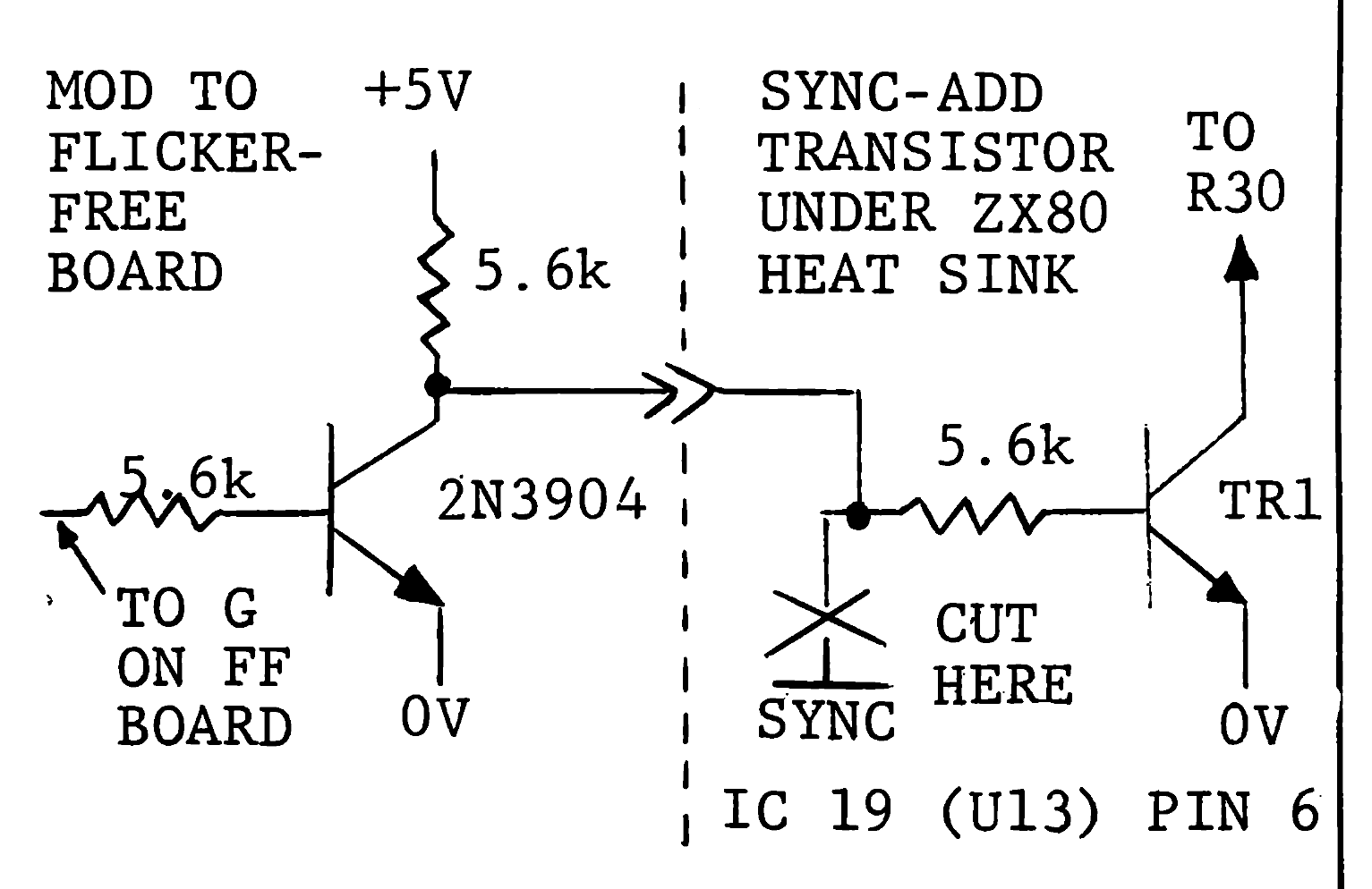
You must add a simple, one-transistor circuit to the mod kit. This provides the SYNC signal needed by the ZX80 (but not shown on the Sinclair schematic). You add only three parts, but the PC board provides no room for them.
Your ZX80 needs one more trace cut and one more connection to the modified flicker-free kit to accept this change. John says: “The sync-add transistor is located to the left of the modulator unit and under the voltage regulator heat sink. Cut the printed circuit going to the 5.6k Ohm resistor which feeds the base of the sync add transistor. Wire the collector of the flicker-free mod’s added transistor to the 5.6k Ohm resistor part of the cut circuit.”