
Here is a project that will let you “burn” (program) EPROMS using your computer. It will handle either the 2764 type (8K bytes) or the 27128 (16K) EPROMs. The text assumes that this is for the TS2068, as this is the machine for which the board was designed. (The circuit works quite nicely with the ZX81/TS1000 also.-ed.)
The 2068 EPROM Programmer is memory mapped at 8192-16383 in the 2764 (8K) mode, and at 0-16383 in the 27128 (16K) mode. The programmer will respond only to a write (POKE) in this address space. If the programmer is installed in the expansion board (or otherwise plugged on the back of the 2068, but the 1000 requires an expansion board due to the size of the PC Board), contains a fresh EPROM, and has 21 VDC applied to its Vpp input line, then it will take any data POKEd into it and store it on EPROM at the address POKEd for the 27128, or at (address POKEd – 8192) for the 2764. The programmer has its own timer and latch circuit, and DOES NOT use the Z80 WAIT NOT control line, so it is compatible with the dynamic memory used in the 2068; there is no possibility of data corruption. Unlike most EPROM programmers, the software required to program an EPROM consists of a simple FOR/NEXT loop with a PAUSE 3 statement after each POKE in the loop to allow the timer on the board to complete its programming cycle. Due to the design of the programmer, data verification from this board is not possible. If verification is desired, it must be performed from a 2068 User Cartridge (procedures for doing so will be covered later). EPROMs with a rated access time of 300 ns or less are recommended for the 2068 computer, although this programmer is capable of programming any speed of EPROM. I should mention that I’ve experienced problems with speed using Intel brand EPROMs, and have read of the same problem with Intel EPROMs used on other computers (the BBC comes to mind immediately), so I recommend against using this brand on the 2068, if possible.
Buying EPROMS
One of the best places I know of to get the EPROMs for this programmer is Microprocessors Unlimited, phone (918) 267-4961. Current price for the 300 ns. Hitachi 27127 is $12.97, and for 2764 it is $5.00.
Static is a NO-NO!
Before we go on to the construction details, a few words about static electricity. STATIC IS THE #1 KILLER OF EPROMS. Yes, static can blow that $12.00, 27128 in no time flat. There is no reason to become “static paranoid” about this though. I recommend the following two rules, which if strictly adhered to will prevent 99% of all static problems:
1: Don’t even look at your computer or any EPROMs without first removing your shoes! Socks are OK, but NEVER wear shoes while working on or near your computer.
2: If you need to ship a board containing EPROMs or other static sensitive MOS parts to me or anyone else, wrap the entire board in aluminum foil. A lot of static can build up in that white packing material and other plastics.
Equipment
1. Use a clean, low-wattage, fine tip soldering pencil.
2. Get a very small diameter 60/40 rosin-core solder to assemble the board.
3. Q-tips and a bottle of acetone or (preferably) non-flammable commercial flux remover.
4. You will need a pair of flush cutting “nippy” cutters (Radio Shack is one source) for cutting component leads after soldering. You might possibly need a small pair of needle-nose pliers to form the resistor and cap leads before installation.
Construction
As usual, there are a number of different approaches you can use to get the circuit working. You can build it on a piece of perf board. If you use this approach, match my component layout as closely as possible, and keep your leads short to prevent problems with stray capacitance. If this is all too much trouble, I supply a two-sided, plated-through board with component placement marked. It comes with or without parts. See the parts list for ordering information. This option will be, by far, the easiest way to get your EPROM programmer working.
If you purchase my bare-board or parts kit, feed-through wire installation is not required, as this board comes with plated-through holes. ALL parts mount on the component side of the board. If you purchase my board, all soldering is done on the “wiring” side of the board.
Step by Step
If you’re building the circuit on perf-board, you’re on your own; follow the schematic, then proceed to Step 7.
STEP 1 – THE SOCKETS
Install all IC sockets onto the board, making sure that their pin 1 ends (labelled “1” or with a notch) are installed at the end marked “1” at each mounting area. Carefully but completely solder them in place. Use extra care at small pads that have PC traces adjacent to them, as it is easy to get a tiny short at these locations; a little extra care here can save a lot of time in troubleshooting. If you wish to use a ZIF (zero insertion force) socket, it should be installed instead of the low-profile socket provided in my parts kit; it is very hard (to say the least) to remove sockets from a plated-through board once installed. The board is laid out to allow plenty of room for the larger ZIF socket. When the sockets have been soldered in, remove all traces of flux with Q-tips and flux remover or acetone. Carefully inspect your work for solder bridges and bad solder joints, and touch up anything that looks at all suspicious.
Eprom Programmer Circuit
(c)1984 The John Oliger Co.
The following is available
Bare PC board @ $12.95
PC w/parts (no EPROMs) @ $25.95
Board, assembled & tested (no EPROMs) @ $33.95
The John Oliger Co.
11601 Whidbey Dr.
Cumberland, IN 46229
All prices are postpaid – USA and Canada
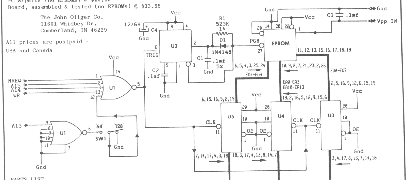
PARTS LIST

U1      74LS260 or 74HC260 dual 5-input NOR gate
U2      555 Timer IC (CA555CE, NE555, LM555, etc.)
U3-U5   74LS374, 74LS377, 74HC374 or 74HC377
C1      .1 uF. mylar capacitor, 5% tolerance or
        better
C2,C3   .1 uF. disc or mylar capacitor
C4      10 uF., 6V. or better tantalum capacitor
R1      523K 1% precision resistor (grn-red-org-org-
        brn) or 1 meg multi-turn pot adjusted with
        DVM
SW1     SPDT ultra-miniature pc mount slide switch
D1      1N4148 switching diode
1 pc    8-pin low profile IC socket
1 pc    14-pin low profile IC socket
3 pcs   20-pin low profile IC socket
1 pc    28-pin low profile IC socket (or user-
        supplied ZIF IC socket)
1 pc    22 AWG by 2" solid red wire
1 pc    22 AWG by 2" solid black wire
STEP 2 – SMALL PARTS
Install all capacitors and resistors onto the board (C1, C2, C3, C4 and R1). Be sure that C1 is in the correct location, as this capacitor is a low-drift, tighter spec part than the other two 0.1 uF. caps in the circuit. (It is the larger 0.1 uF. cap in my parts kit.) Also insure that the red (+) end of C4 is installed at the pad marked “+” on the board.
STEP 3 – SWITCH AND DIODE
Install switch SW1 in its correct location on the board. It should be oriented so as not to cover up too much of the “128” legend etched on the board. Install diode D1, with its cathode (banded) end at the same side as the line on the diode symbol on the board. This results in the diode’s banded end being on the left side of the diode as seen looking down at the board with its edge traces toward you.
STEP 4 – Vpp INPUT WIRES
Prepare 2 pieces of 22 or 24 AWG solid wires (one red, one black), 2 inches long, by stripping 1/4″ of insulation from one end of each, and 3/4″ from the opposite end. Bend the longer stripped end of each wire into an “O” with small needle-nose pliers. (This has already been done to the wires supplied in the parts kit.) Install these wires on the board by inserting each shorter stripped end into its respective pad on the component side of the board, and soldering them on the opposite side. The red wire goes into the pad marked “Vpp,” and the black wire goes to the pad marked “GND” at the top of the board. The free end of these “Vpp input wires” should be bent to extend above the board (away from the edge traces) for easy attachment to the Vpp supply when programming an EPROM.
STEP 5 – CLEAN-UP
Clean off all traces of flux from new soldering, and carefully perform a final inspection. Touch up your work as needed. Soldering on the board is now complete!
STEP 6 – INSTALL IC’s
Install all IC’s (U1-U5) in their respective sockets per the schematic. Because each different type of IC has a different number of pins, it is very hard to get the IC’s in the wrong sockets. Be VERY sure, however, that ALL pins of each IC actually enter their respective contacts, and that pin 1 is located at the same end as the “1” label on the board. Beware when installing an EPROM later on, because its pin 1 is on the OPPOSITE end of the socket in relation to U1-U5, usually resulting in its part number printing being upside down when the board is installed. Your programmer is now ready for testing!
STEP 7 – THE SMOKE TEST
I recommend testing the board before actually trying to program an EPROM. A logic probe is recommended, but you will be able to do some of the tests even with only a voltmeter. With SW1 in its “64” position, verify that pin 1 of U3, U4 and U5 each receives a pulse when any POKE is made to memory from 8192 to 16383d. Now key in LET a=0 (ENTER). Switch SW1 to its “128” position and key in POKE a,a (ENTER) while monitoring pin 1 of U3. You should receive a pulse on your logic probe. Now use your logic probe or a voltmeter to verify that each used output (see schematic) of U3, U4 and U5 is at a logic low. If not, check the board for errors. Now flip SW1 to its “64” position and enter POKE 16383,255. Use your logic probe or voltmeter again on all these latch outputs, this time verifying a logic high on each used output. (Don’t be confused by a wrong logic level on any outputs that are not used; there are a few such in this circuit.) If you don’t get a logic high on every used output, check for errors to find out why. If all is well, your board has passed the “smoke test.”
Power Supply Notes
Although the John Oliger Co., Vpp power supply is recommended for use with this programmer, you can also use your own power supply for Vpp if it is a regulated, variable supply capable of covering the voltage range from 4.4 to 21 VDC. You will also need a voltmeter to use with it that covers this range.
To use it with this programmer, you have to preset it to turn on at 4.5 VDC on power-up. Then, when the instructions say to connect the Vpp supply to the programmer, you connect instead the combination of your preset supply and voltmeter. When the instructions say to plug in the Vpp supply, you should plug in or switch on your own supply, which at this time should be set to 4.5 VDC. When the instructions say to switch the Vpp supply to “Vpp,” you should then carefully increase the voltage on your supply to 21 VDC. Use care here not to overshoot 21V, because the EPROM cannot handle anything, even for an instant, greater than 22 VDC. Any overshoot higher than this WILL destroy your EPROM! (Just connecting the power supply preset to 21 VDC when ready or switching the Vpp input line with a switch will usually destroy an EPROM due to the initial surge!)
When the documentation says to switch the Vpp supply back to 4.4V, you should lower your supply’s voltage to about 4.5 VDC. And, of course, when it says to unplug the Vpp supply you should unplug or switch off your supply.
You will find that there is nothing wrong with this arrangement if you only infrequently program EPROMs on this board, but are advised, if for nothing else but convenience, to obtain the Oliger Vpp supply if you find yourself programming EPROMs a lot.
Burning a 2764 Eprom
When programming 2764 EPROMs, use the “64” position of SW1 and POKE your data to locations 8192-16383. The programmer’s base address in this mode is 8192, so a POKE to 8192 goes to the EPROM’s location 0, POKEing 8193 goes to the EPROM’s location 1, etc. When programing an EPROM on this programmer, the EPROM can be thought of as the famous “write-only memory,” which is what it really is at this point!
Install a new or erased 2764 EPROM in the EPROM socket of the programmer, with the computer off and programmer removed from the expansion board. Be sure that pin 1 is installed in the socket at the same end as the “1” etched on the board. Note that the EPROM has its pin 1 to the right, while the support chips on the board all have pin 1 to the left. BE SURE it’s plugged in the right way. It will most certainly be destroyed if you try to program it when it is installed backwards! (Although I have not yet mixed up pin 1 on the 2068, I do know that the 1000 will not come up running with the eprom in backwards, let alone be able to program it.-ed.)
Now plug the programmer into your 2068 Expansion Board and attach the Vpp supply’s output clips to the programmer board’s Vpp input wires.
BE SURE to get polarity right –
“Gnd” to the supply ground, and
“Vpp” to the (positive) Vpp output
of the supply.
Turn on your TS2068 computer. Set the Vpp supply’s switches to “4.4” and “21,” (There is also a 25V position for programming a 2716 eprom, using a different board.-ed) and plug in the supply. Its green “power on” LED should light, but its red “Vpp” LED should remain off. You are now ready to program your EPROM.
To program a 2764 for use on the 2068 User Cartridge, refer to the program and instructions included with your Cartridge. To program a 2764 with data, such as a machine code program, LOAD or key in your code into free RAM at this time. When the desired data is in RAM, use a FOR/NEXT loop to POKE the data into the EPROM. An example follows:
This subroutine will take the contents of RAM from 32768-40959 (8000-9FFF) and put it on a 2764 EPROM. The programmer’s SW1 must be set to “64” or errors will occur in the first few locations. Key in the program with the Vpp supply at 4.4V. Flip your Vpp switch to “Vpp” only right before you GOTO 1.
10 LET x=8192             ;Set base addr of pgmr
20 FOR n=32768 TO 40959   ;Data limits
30 POKE x,PEEK n :        ;Program 1 byte
   LET x=x+1               and point at next one
40 PAUSE 3 :              ;Wait for pgmr to time out
   PRINT AT 9,9;x          and print data pgmd.
50 Next n : BEEP 2,2      ;loop back until done
                           beep if complete
When the TS2068 is done storing the data on EPROM, as shown by the error code or BEEP, switch the Vpp supply back to 4.4 V. Now unplug the Vpp supply and then switch off the computer. Remove the programmer board from the expansion board, and the EPROM from the programmer. Your 2764 is now programmed.
Program the 27128
On the 2068, programming the 27128 is somewhat more involved than 2764’s because the home ROM contains a routine that writes garbage to the first four locations of itself when handling a number from BASIC. This usually results in the EPROM’s 4th location (0003h) being programmed a zero, despite attempts at other values. NOTE: This does not happen when programming 2764’s with SW1 in the “64” position, so no special programming care is needed with 2764’s.
There IS a way around the problem, but care must be exercised nontheless. An EPROM CANNOT be programmed if the Vpp supply is in its 4.4V position. Also, reading numbers from a DATA list or using a variable that has been set up using a LET statement with Vpp at 4.4V does not cause the ROM to write its garbage. Thus the following two routines have been written to program 27128’s on this programmer. The first will take data from RAM locations 32768-49151 and program it on a 27128 EPROM. The second routine replaces the User Cartridge documentation routine when programming 27128 EPROMs with BASIC programs for the User Cartridge.
Important things to remember with 27128’s are:
1: Keep the 4.4/Vpp switch in the 4.4 Volt position AT ALL TIMES when entering BASIC lines or ANYTHING with numbers from BASIC.
2: Switch the Vpp supply to “Vpp” right before you actually start the program. DO NOT start the program with GOTO (number), use GOTO (variable) instead, with the variable equal to the starting line number using a (LET variable = number) statement while the Vpp supply is still in its 4.4 V setting.
3: Type in the routine used EXACTLY as listed, except for the numbers listed in the DATA statement as being set for the particular application.
4: Be sure SW1 is in its “128” position.
Other than the added care that must be taken, the base address starting at 0, and the 16K capacity of the 27128, programming a 27128 EPROM is just like burning a 2764. I suggest burning only 2764’s until you get the feel for the procedure, then adding to your expertise by going on to the 27128.
Listing 1:
This routine takes the contents of RAM from 32768 to 49151 and programs it onto a 27128 EPROM. This data could be machine code loaded here from tape, another EPROM mapped 32768-49151, or data POKEd into memory in some manner.
9990 RESTORE data: READ src: READ end: READ dest: READ one: READ three: READ loop: READ line: READ col
9992 POKE dest,PEEK src
9993 PAUSE three
9994 LET src=src+one
9995 LET dest=dest+one
9996 PRINT AT line,col;dest
9997 IF src<=end THEN GO TO loop
9999 DATA 32768,49151,0,1,3,9992,10,13
     (first 2 numbers can be changed if data is
     elsewhere in memory)
BEFORE RUNNING THIS SUBROUTINE KEY IN: LET p=9990: LET data=9999 (Enter) then flip SW1 to “Vpp” and key in GO TO p (Enter).
Listing 2
This subroutine takes the place of the one given in the 2068 User Cartridge documentation when programming 27128 EPROMs. (PEEK 23627+PEEK 23628*256)-1 cannot exceed 43085 for one 27128 or 59469 for use with two 27128’s. The 2nd data item in line 9999 (xxxx) should be the number written down from the User Cart documentation if 43085 or less. If greater than 43085, use 43085 for the first EPROM, and for the second EPROM use 43086 to replace 26710 in line 9999, and the number written down to replace the xxxx. Note: If the number was greater than 43085 but less than 51278, you can use a 2764 for the 2nd EPROM and save some money. Just use the diodes for the 27128 connected to the 32 and 40 LS138 outputs, and a wire-wrap jumper from the 48 output to the Eb pad on the User Cartridge board.
9980 RESTORE data: READ dest: READ one: READ three: READ eight: READ next: READ data
9982 READ z: POKE dest,z: LET dest=dest+one
9984 PAUSE three
9986 IF dest<eight THEN GO TO next
9988 DATA 0,1,3,8,9982,9999
9989 DATA 1,2,8,128,15,1,0,0
9990 RESTORE data: READ src: READ end: READ loop: READ line: READ col
9992 POKE dest,PEEK src
9993 PAUSE three
9994 LET src=src+one
9995 LET dest=dest+one
9996 PRINT AT line,col;dest
9997 IF src<=end THEN GO TO loop
9999 DATA 26710,xxxx,9992,10,13
TO START THIS SUBROUTINE, KEY IN: LET p=9980: LET data=9988 (Enter) then switch Vpp supply to “Vpp” position and key in: GO TO p (Enter).