A couple of months ago one of our members ,Dave Battershill from Calgary, told me about a Monitor available from Sears department stores(Note: Not their catalogue mail-order dept)
This monitor works as a regular 14-inch TV, and also provides a composite video, and an RGB input.Additionally, it has a push-button green screen capability. All this for the price of $550 (Sometimes on sale for $500)
I had some difficulty initially, because I could not get color on the monitor with my 2068 computer. However by adjusting some variable resistors and capacitors in the computer per an article in the magazine TIMELINEZ I was successful. I now have a monitor working in the RGB mode and it is simply marvellous. I can heartily recomment it.
I am incorporating one of Dave’s letters in this article as an easy way of providing technical details of what is involved in hooking this model of monitor to your TS2068.
Copy of Dave’s letter follows:
Dear George:
Recently received the latest newsletter and found your account of the proceedings rather interesting. In the last letter to you I included two different RGB interface diagrams; the Timex-designed model and the model from E. Arthur Brown. In your account of the proceedings with the Sears monitor I am not sure that I clarified to you that I was tickled pink with the screen clarity and colors using the RGB interface and the Sears monitor in the RGB mode. In the other two modes, namely (1)TV signal(rf) using the little switch and matching box; and (2) composite video; the 2068 has to be adjusted to provide the best signal.
At the time of your phone call to me I had not received the TIMELINEZ article with the program “PATTERNS” and the adjustment procedures. I would say that every 2068 (including mine) would need these adjustments.
As received, I thought my 2068 had an acceptable screen but until I had keyed in “PATTERNS” I was unaware of the shortcomings my 2068 had in modes 1 and 2.
Re the RGB interfaces– I have built the Timex model and it works fine with the errors to the diagram corrected as I indicated earlier. However I built it as a board to plug into the edge connector at the back of the 2068. This makes it difficult (but not impossible) to connect other peripherals such as a printer or modem. Of course the Timex model could be built on a very small board and tucked inside the computer similar to the E. Arthur Brown model. The E. Brown model would be my choice. It should be easy to build with point to point wiring, and of course if you use it with a monitor that accepts negative-going sync signals (such as the Sears model is set at the factory for) then you do not need the jumpers from IC pin 1 to IC pin 10, and IC pin 3 to IC pin 8, as these only add in another inverter each to invert the two output signals one more time each to positive polarity.
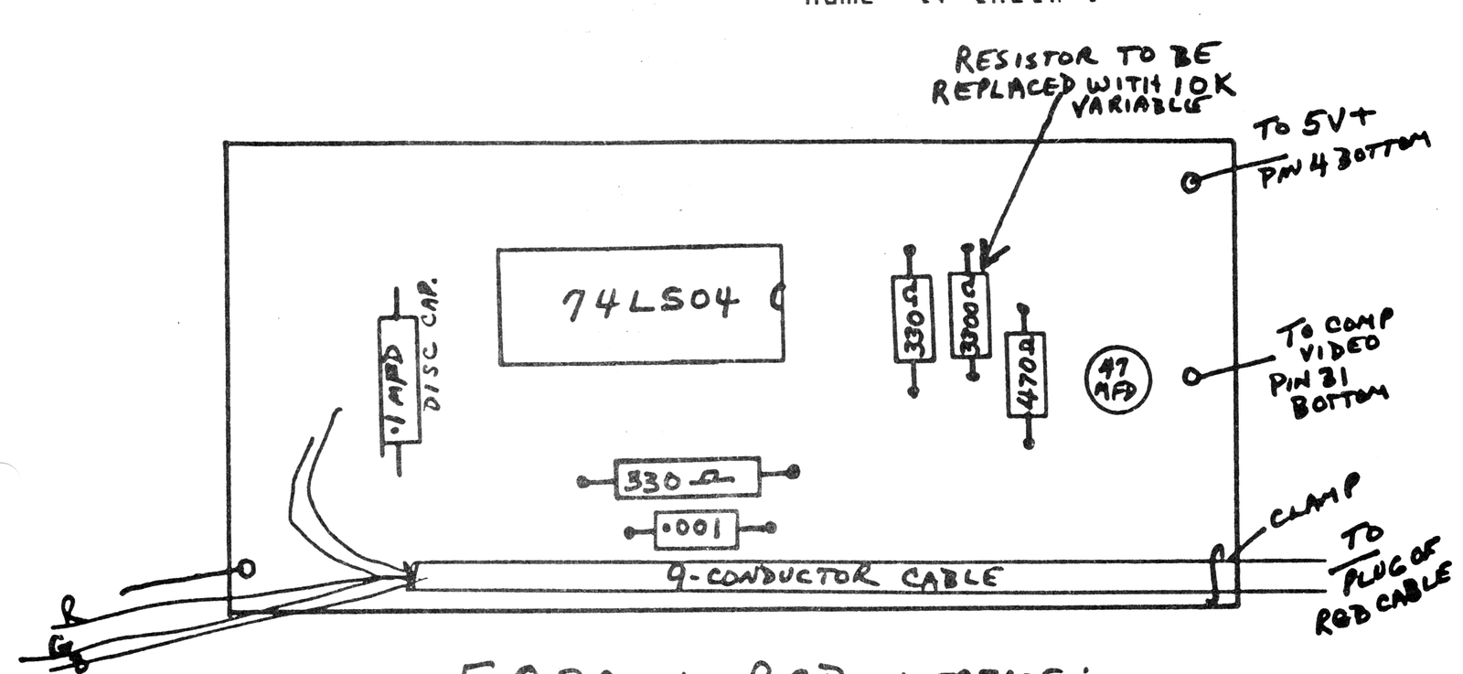
There is one other small defect that has turned up with the E. Arthur Brown model… When actually connected into the circuit and operating, the interface exhibits some unacceptable instability with the composite sync, in that single color or 2/3 color screens such as the white screen with two copyright lines , or Flight Simulator blue border, yellow screen with choices 1, 2, or 3 and Wind Effects Y or N; come up fine but have a little jiggle. However when the Flight Simulation full cockpit screen comes up, the screen immediately skews sideways and then fades out. To correct this problem, the manufacturer advises,replace the 330 ohm resistor that is parallel to (i.e. across) the 3300 ohm resistor, with an ADJUSTABLE 10K thumbwheel pot.
I have not tried this yet but feel reasonably sure that this correction will do the trick. I show a diagram below, of the physical layout of the E.A.B. model.(top side). The bottom side has flat point to point wiring and is then covered up by a sticky two-sided tape such as Radio Shack’s #64-2344.
P.S. The 9-conductor cable extends only 6″ beyond the board and I have attached a 9-pin female socket (Radio Shack #276-1538) to this end with pins as follows.
Pin No.   Signal
=======   ======

   1      Ground
   2      Ground
   3      Red signal
   4      Green Signal
   5      Blue Signal
   6      Intensity
   7      Sound
   8      V/H Comp. Sync
   9      Vert. Sync
Also I have utilized a Sears 3-foot #57-14544 (Monitor to IBM computer)cable that is connected as follows::
RS 9-pin   Signal      8-pin male
 plug                  EIAJ plug
========   ======      ==========

   1       ground          5
   2       ground          6
   3       red             2
   4       green           3
   5       blue            4
   6       intensity       1

   7  not connected-
        could be used for sound

   8       V/H comp.       7

   9       Vert Sync       8
You could easily make your own substitute for the Sears 57-14544 computer cable, or, to save costs,install a longer(say a 3 or 4-foot) 9-conductor cable onto the RGB interface and just add an EIAJ plug(male) at the far end. A suitable plug would be a Frietag Electronic Video #2284 8-pole Stecker.
Merry Xmas Dave.
End of letter
My comments on subject:GFC
I used the E.A.B. RGB interface and the Radio Shack 9-pin male plug as noted. I shortened the E.A.B. leads, cut a hole in the rear of the computer case(bottom section) and mounted the RS plug to the case. I bought the Sears connecting cable,(cost $29.95) rather than making up my own.
The Brown instructions are just a bit vague. I had to remove the computer chassis to inspect the underside to determine which pins to make connection to. Since Brown does not know which monitor you are going to use the notes by Dave will prove useful.
There are five ‘pots’ you can adjust to improve the quality of the picture on the screen. The three located near the BEEP speaker are variable resistors having a single 260 degree turn. There is a variable capacitor inside the metal box at the rear left corner and another one approx. 2″ to the rear of the ‘0’ key. Both the capacitors can be identified; they are orange colored.
One complete revolution of the capacitors seems to bring them back to their starting point. Marking the initial position of all these before touching them is a good idea; but in practice it does not seem that important. One caution I would make is to use a wooden or plastic tool, not a metal one. After all, it is a piece of electronic gear you are working on. You will find it awkward to hold the case open while doing these adjustments. While mounting the interface I removed the top keyboard. This was not hard, except the keyboard ribbon cable is a tight fit into the socket on the circuit board, and requires a firm pull to remove.
Adjusting the ‘pot’ under the metal can will result in some color shift toward a black and white screen.
I found that adjusting the other orange ‘pot’ reduced the Wrigglies’ on the screen somewhat(but not entirely).
The adjustment of one of the resistors (the lefthand one of the pair at the rear of speaker) is somewhat critical. You may have to tweak it carefully to get the right spot. In fact you may feel it advisable not to touch this one at all.The screen tears etc. if not right. The other two are non-critical but they are inter-active and will require some fiddling before you are happy.
I have not made the changes to the Brown interface, as suggested by Dave. I must confess to some loss of nerve. The thing is working so well that I do not want to tempt fate.
The error that Dave refers to is one that is in the RGB interface circuit shown in the TS2068 technical manual page62. Transister Q3 is shown incorrectly as an NPN, whereas it is actually a PNP. Dave also says that R5 may be too small; that he has used a 10K variable thumbwheel resistor in place of the fixed 1000 ohms resistor.
There are some drawbacks to the monitor that I have not resolved,however.
Firstly, when I use it with my ZX81 (yes, I still like the ZX81) in the TV or composite video mode the screen fades off to blackness during SAVEs and LOADs, and recovers only when the LOAD/SAVE function is complete.
At the same time, it loads the MIKE lead so that the SAVEd signal is too weak to LOAD properly. I have to disconnect the monitor while SAVEing.Very irritating, I’m sure I will hear of a solution some day.
Secondly, if using the TV or composite video inputs the sharpness and color are no better Than that of a regular TV set. You are definitely buying this monitor for the superior color and sharpness the RGB interface offers.
I have placed the “PATTERN” program mentioned in Dave’s letter on tape #16 under the name “tv check”.