
or, the joy of using interrupts on your computer
Thanks for the ooh’s and ahh’s over last month’s interrupt driven sprite program. Even though he doesn’t do all that much, there is a certain novelty to seeing his happy face bouncing around the screen while we do other things. Although I said I’d explain that program this time, there are two big guys at the door who’ve “persuaded” me to take a little detour. (Or at least, that’s the way it seems. Don’t worry, we’ll get back to the sprites sometime soon.)
Actually, I’ve gotten some complaints that I’m “dragging my feet” about discussing the Non Maskable Interrupt (NMI, for short). This may be so, and I DO listen carefully to what you have to say. In any case, since some of you haven’t yet gotten around to entering that sprite program (summertime you know) this will give you a chance to get caught up. Furthermore, using the NMI will require you to build a bit of non-trivial hardware to get around a bug in the ROM. In this article, I’ll show you what you need. You’ll have a month to build it, and I’ll show you how to use it next time. (Hopefully, we’ll talk about sprites too.)
The hardware you’ll need will include the “NMI Switch” shown in this article and the Universal LROS/AROS Development Board described in the November 1984 issue of SINCUS NEWS. The schematic will be reprinted here if space permits. (Those of you who joined SINCUS since the publication of that article who want a copy of that article should contact me personally. (Enclose a stamped self addressed envelope. PLEASE DON’T SEND ANY MONEY for copying just yet.)
The LROS/AROS Development Board lets you run RAM in your cartridge bank. If you have a tape of the code from a Spectrum ROM, you can also have a SPECTRUM emulator. If you instead insert the code from the TS2068 home ROM, you can change the code to fix the NMI bug (or do whatever other tricks your hacking heart desires!) Note that the TS2068 code was written to be run in the cartridge bank. This causes some minor, but tolerable, problems. The Spectrum ROM codes run without a hitch.
In the mode we’ll be using the board, it won’t be compatible with an EMU-type emulator, or my own “Extra Simple Spectrum Emulator”, because they all try to use the same memory space. Since the LROS/AROS Development Board can already function as a Spectrum emulator, this incompatibility is not a problem. (In case anyone’s interested, it was by simulating the Spectrum ROM on this board that I originally became convinced the the “Extra Simple Spectrum Emulator” was feasible.
If you’re really good at soldering, you can build this board to fit the cartridge slot; mine does, and its quite handy. However, since the NMI switch will have to be built to the rear connector (the necessary NMI line doesn’t appear at the cartridge slot) it may be worthwhile to build the whole thing to the rear connector.
Since publication of the article on the board a year ago, the price of the 8kx8 RAM chips it uses have fallen from $30 to under 5 bucks a piece. (anyone who taunts me about what I must have spent to build the original board will get no further help from me!) Consequently, this gadget, which can be run as a Spectrum emulator (with the proper code), runs HOT Z-AROS) Ray Kingsley at least USED to sell the code on cassette), and can be used to develop your own cartridge programs, is already a worthwhile gadget to have around. Used with the NMI switch, its dynamite!
Originally, I’d hoped that readers would supply some programs for use with this board, but we have a chicken- and-egg situation. Without programs, only a few readers have boards, and without many readers using them, not too many programs were developed. Never fear, I’ve been digging down into my old notes to get the info we need to start things going. Wait’ll you see!
Interrupts? Oh, yes, we were talking about them, weren’t we? Basically, the NMI works as follows. When the NMI line at the rear connector is brought MOMENTARILY to ground, the computer stops what it’s doing and starts executing code at H0066. So that the computer doesn’t lose its place, the address where it left off goes on the machine stack. Also, the status of the maskable interrupt is saved, and then the maskable interrupt is disabled.

The NMI cannot be disabled, so we can use it to interrupt most programs. (Some Spectrum programs will crash themselves if they “suspect” that we’ve added NMI capabilities. This is because the NMI is a useful tool for “hacking in” to copy protected programs.) In order to make NMI work for all programs, our LROS/AROS board would have to be a good deal more complicated, and the number of “NMI protected” programs is very small. I don’t see the benefit in doing so at present.
When we’re done servicing our NMI, we want to sent the computer back to what it was doing. All that’s necessary is to restore whatever registers we’ve changed, and then use a RETN instruction. We don’t use an ordinary RET in this case because it does not restore the status of the maskable interrupt as RETN does.
This all looks very nice, but there’s a problem; address H0066 is in the ROM, and the ROM code there has a bug. (Whether or not the bug is intentional is subject to some debate.) What it SHOULD have done is as follows. If memory locations H5CB0/1 (23728/9 decimal) contain a non-zero address, that address would be jumped to. If, instead both locations contain zeros, the interrupt routine would simple return via RETN. Unfortunately, the ROM has it coded the other way around. The jump will only occur if these locations contain zeros. As such, the ROM code reduces the powerful nmi function to a reset switch which can disable the software.
The good news is that we need to change only one byte to fix the program. Two ways to do this come readily to mind. WE can build a circuit that disables the computer memory when the “bugfull” byte is being addressed, and then inserts the proper byte on the data bus. Alternately, we can build a circuit that completely replaces the ROM and its code. The second solution only costs a bit more, but you can do much more with it. Also, it’s already been designed and debugged; it’s the LROS/AROS Development Board. It should be noted that the board has been designed to accommodate RAM, ROM, or EEPROM. Make sure you outfit it with 6264 RAM chips.
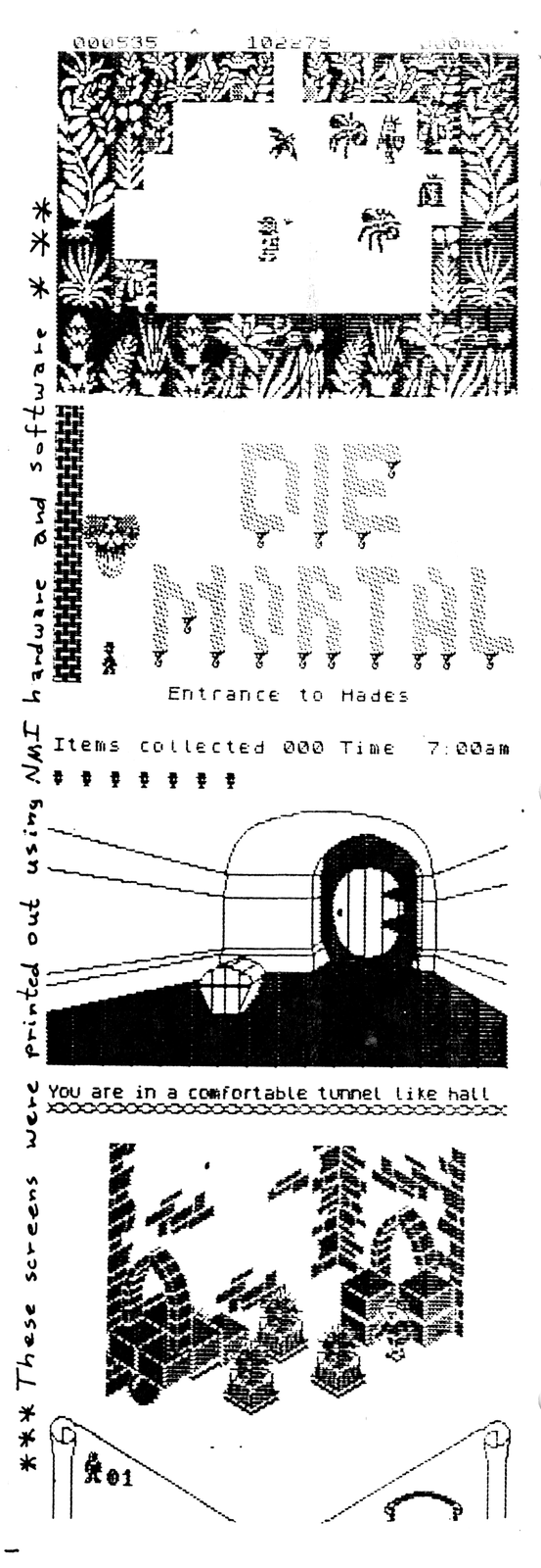
Remember that interrupt driven print-screen program we used to play around with? Many of you discovered that it worked fine with BASIC, but that many commercial programs disabled the maskable interrupt, rendering it useless. An NMI version can’t be disabled, and I’ve included some sample printouts to “wet your appetite”. Can you identify the four Spectrum games that match the illustrations? How may of you “game Freaks” would like to make a full screen printed map of the “SW” jungle, or the “JSW” mansion? Now its easy. (Provided you can get at each screen in the first place.)
Get that hardware built, and we’ll see how to use it next time. As always, you’re welcome to contact me, Wes Brzozowski, [address omitted]. If you wish, feel free to call (Not collect, and before 9:00 P. M. Eastern time, please) at [phone number omitted]. Happy Computing.