
THIS simple, low-cost project permits you to switch on and off under program control up to four 5 amp loads at up to 110 volts. Because of the limitations of the connectors used, the total of the four loads should not exceed 5 amps.
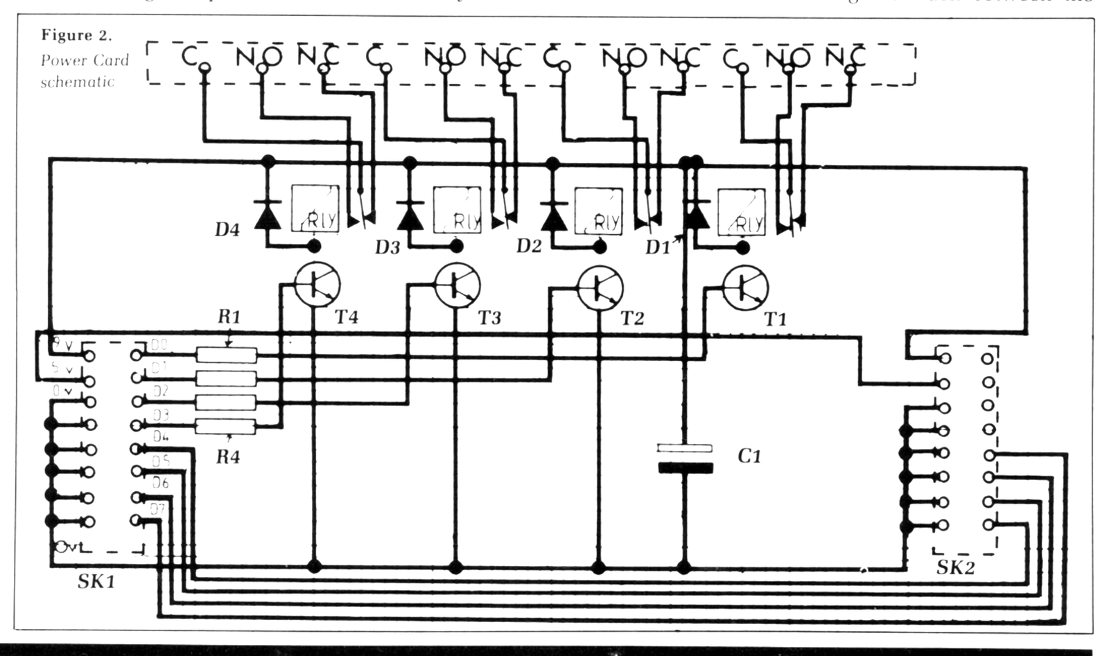
The Power Card is controlled via any user output port such as the Latch Card. It is designed to be plugged right into the Latch Card. An interface is required between the Power Card and the T/S,ZX, and, in lieu of the Latch Card, any interface that will provide an 8-bit output (one only) will do the job; there must be a dozen such devices available.
Suitable applications for the Power Card include switching lamps, aquarium heaters, electric motors, cassette recorders, and model railway points. The warning is that it should not be used to switch unattended electric heaters.
If you build it in time, you can dazzle and amaze your friends and neighbors by using your computer to control your Christmas tree lights. Used with an add-on sound board, you could even have your lights flash in time with music, such as Christmas carols.
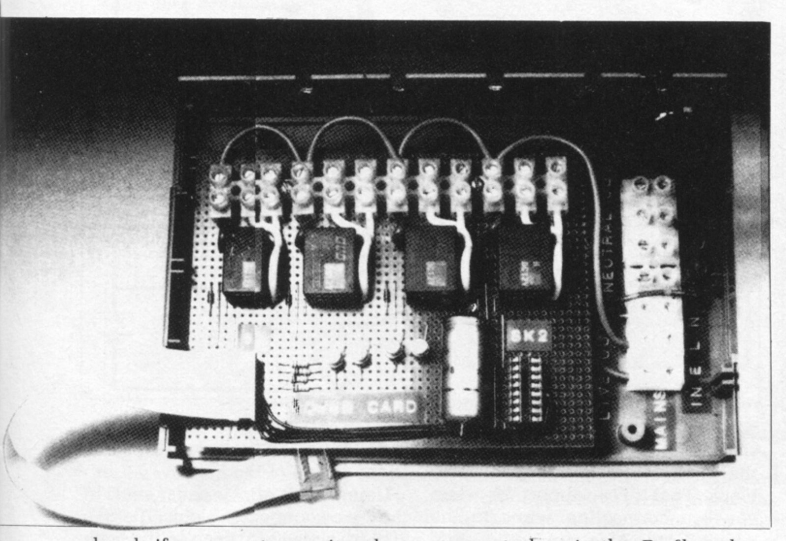
You will see that the circuit board has been mounted in a stout plastic Perfcase; that is essential if the Power Card is to be used to switch mains voltages. On the other hand, if you are to use it only to control your model trains, the box can be omitted and the cost of the project will be almost halved.
COMPONENTS
Qty  Item
2    16-pin dual in-line socket — SK1,
     SK2
1    Perfboard 3¾-in. x 5-in. (10347)
4    10 amp change-over 12V coil
     relays — Rly 1 . . . Rly 4 (10 amp
     mains relay — VX97F)
4    BC107B transistors — T . . . T
4    1 Kohm resistor — R . . . R
4    1N914 diode — D . . . D
1    100m 16V capacitor — C
1    6BA solder tag
1    12-way connector block (5 amp
     rating)
1    7-way connector block (5 amp
     rating)
1    Perf. case 202-21037L type 214
     180mm. x 120mm. x 40mm. con-
     necting wire
To connect the Power Card to a user port you need either two 16-pin dual in-line header plugs and one 1-ft. 16-way ribbon cable or one 16-pin DIL plug to 16-pin plug cable assembly. The header plugs and ribbon cable should be available from any good component shop.
Note: If Vero products are not available from your local supplier, you may substitute Vector, GC or similar manufacturer’s products.
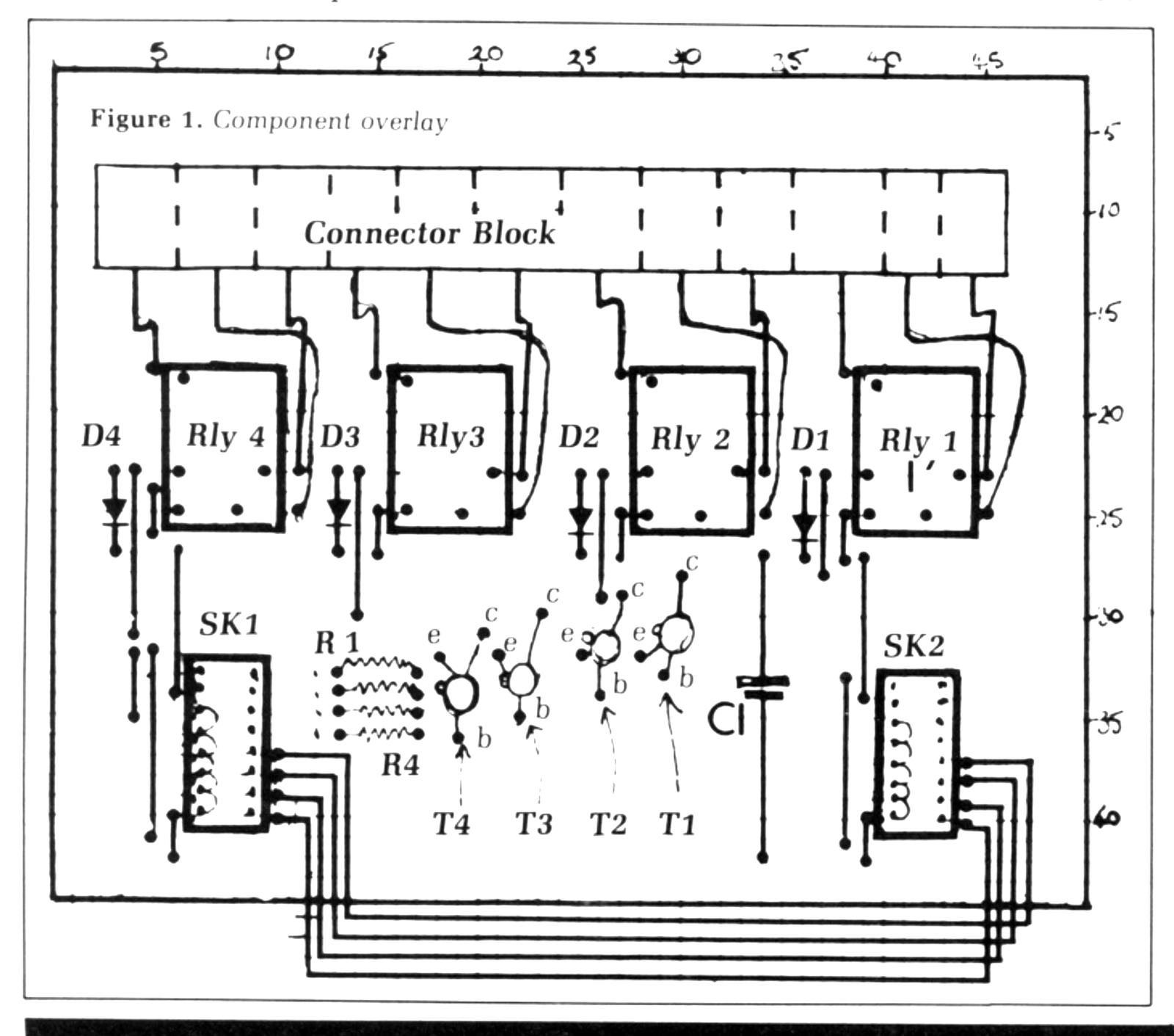
The Power Card is built on a standard-sized piece of Perfboard. Insert the big components in the correct place in the Perfboard using the component overlay diagram in Figure 1 as a guide, and solder them in place. Then work your way down to the small components; it is easier to have the locations correct that way.
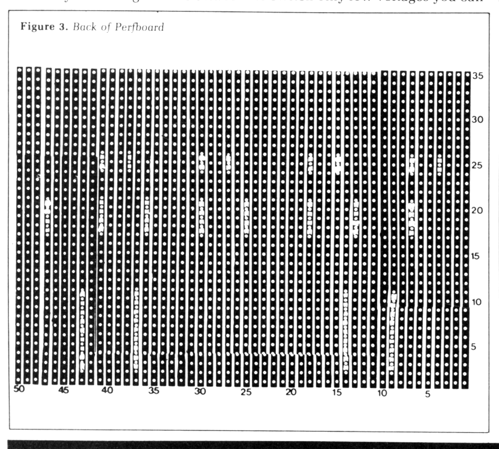
When all the components have been soldered in place and the excess leads have been cropped off, use a 1/8-in. twist drill held in your fingers to cut the tracks in the places indicated. Although this is the opposite way of constructing things from that usually recommended, if the tracks are cut before fitting there is great difficulty in finding the correct locations.
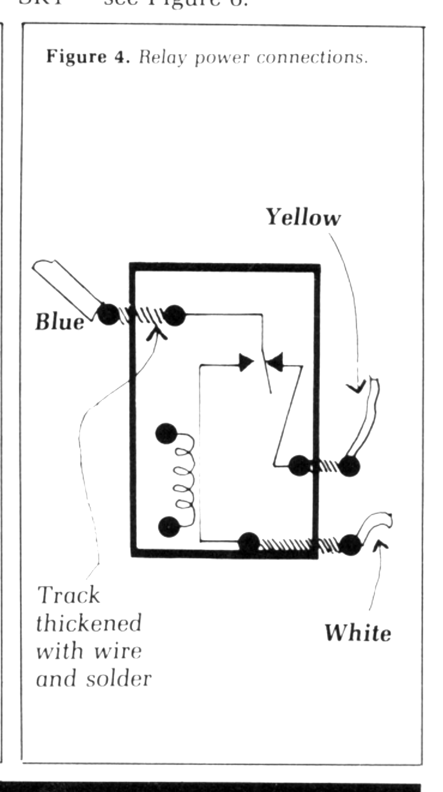
Having fitted all the components, mount the 12-way connector block using two 6BA nuts and bolts or stick it down using sticky pads. When it is in place, use thick insulated wire to put in the links between the connector block and the relays. Use blue for the common connectors, yellow for the normally closed ones and white for the normally open connection on each relay.
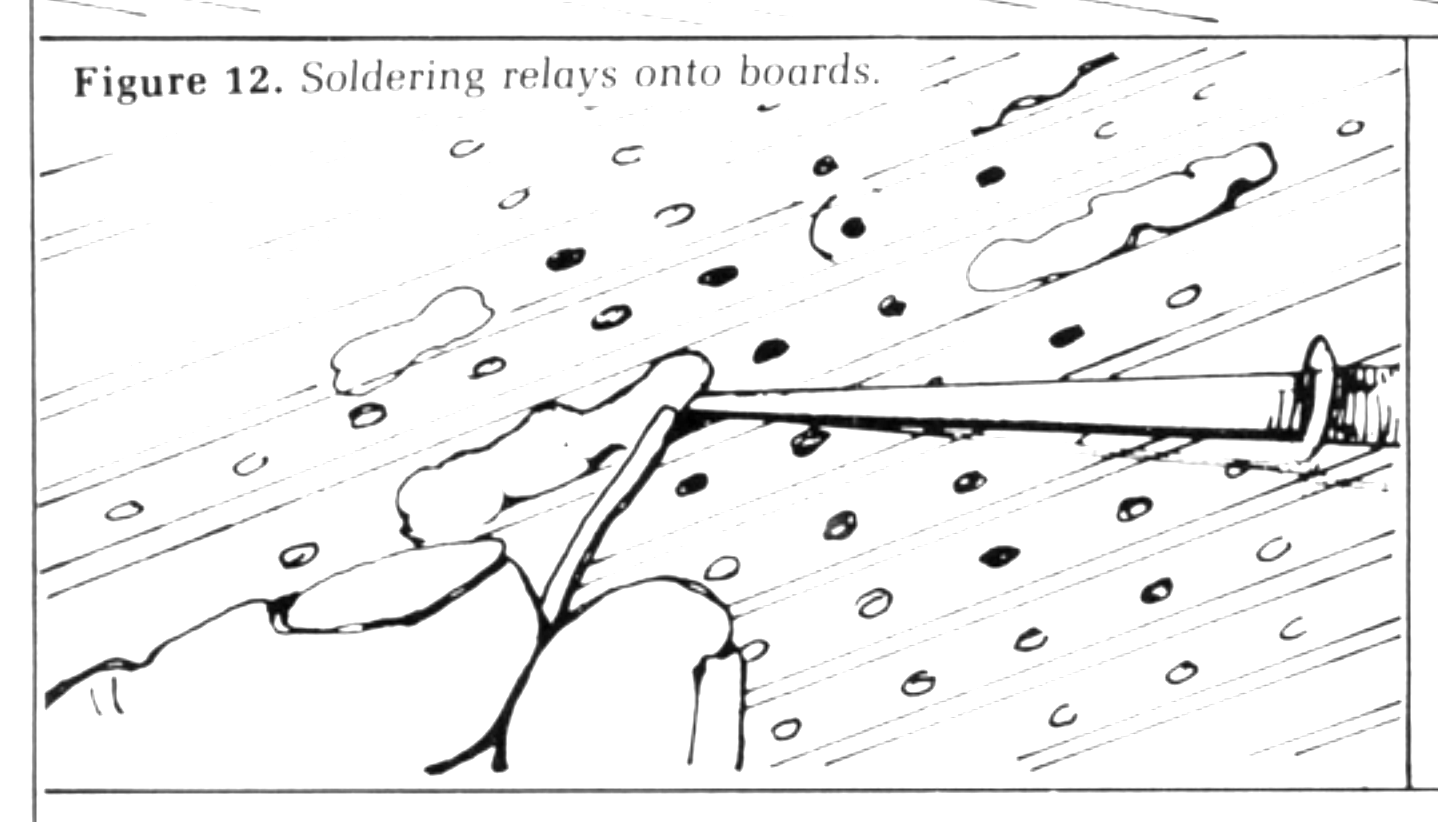
Where the links enter the Perfboard, make sure that there is a good solder connection between the link and the relay connection. For the normally open connection (white), lay an offcut of component wire along the track between the white link and the relay connection and solder it in place to give a good, thick connection. Vero-tracks by themselves will burn out if you try to put 5 amps through them.
The Power Card uses only the lowest four bits of the output latch so you can use the upper four bits to control something else. If the unused upper four bits is routed along with the 9V, 5V and 0V lines to SK2, you can plug in something else there — perhaps another Power Card — but in that case it would be advisable to route the unused upper four bits to the lower four-bit positions of SK2 and then the second Power Card should be identical to the first; otherwise on the second card the four base resistors would need to go to bits 4 to 7, rather than bits 0 to 3.
If you do not want to use the upper four bits, you can omit SK2 and its interconnecting wires. One point you may notice — SK1 and SK2 are one way round in the photograph and the other way round on the drawings. The drawings are correct. Having assembled all the circuit board, there must be some way of holding it in the box. A piece of 3/8-in. balsa, 1-in. x 5-in. can be stuck, using sticky pads, to the board under the connector block. That gives support for when you are connecting wires to the Power Card. Also you could stick ¼-in. x 1-in. pieces of 3/8-in. balsa underneath SK1 and SK2 to give them some support, again using sticky pads.
If you are to use the Power Card to switch only low voltages you can leave it at that but for mains the box is needed, with the balsa feet stuck to the inside of the box.
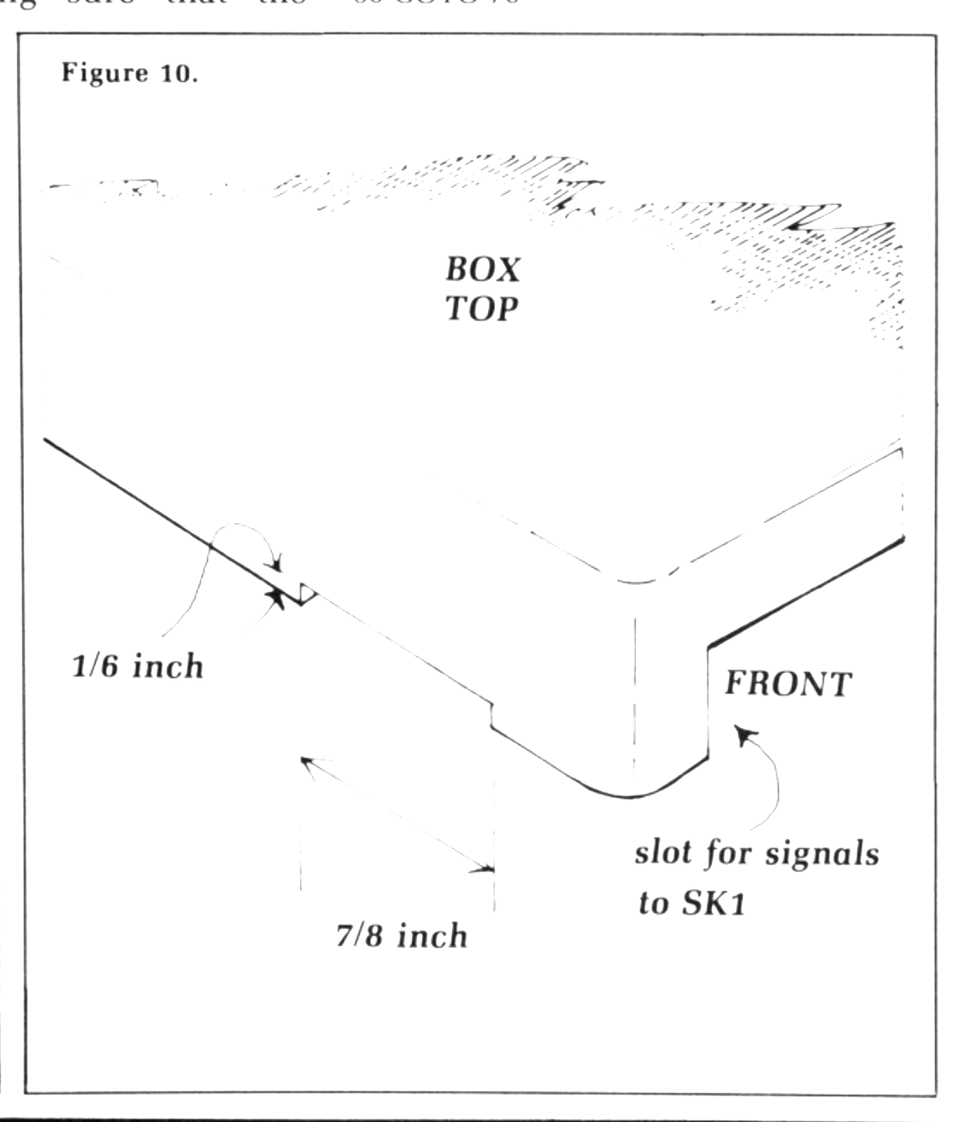
Using more sticky pads, stick in the 7-way connector block. File five 3/16-in. slots ½-in. deep in the back panel and make sure they are smooth and then attach a solder tag with a 6BA nut and bolt. Then cut a slot in the left-hand side of the top of the box (by SK1) for the input to SK1 — see Figure 6.
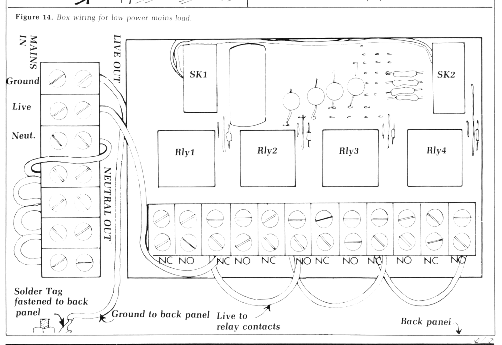
The box wiring is shown in Figure 7 and it should be done in thick wire which will carry 5 amps. Then the mains A.C. supply wires can be wired into the three connectors marked Mains A.C. In, Ground, Live and Neutral. The four loads can each be wired between one of the neutral out connectors and one of the four NO — normally open — connectors by relays.
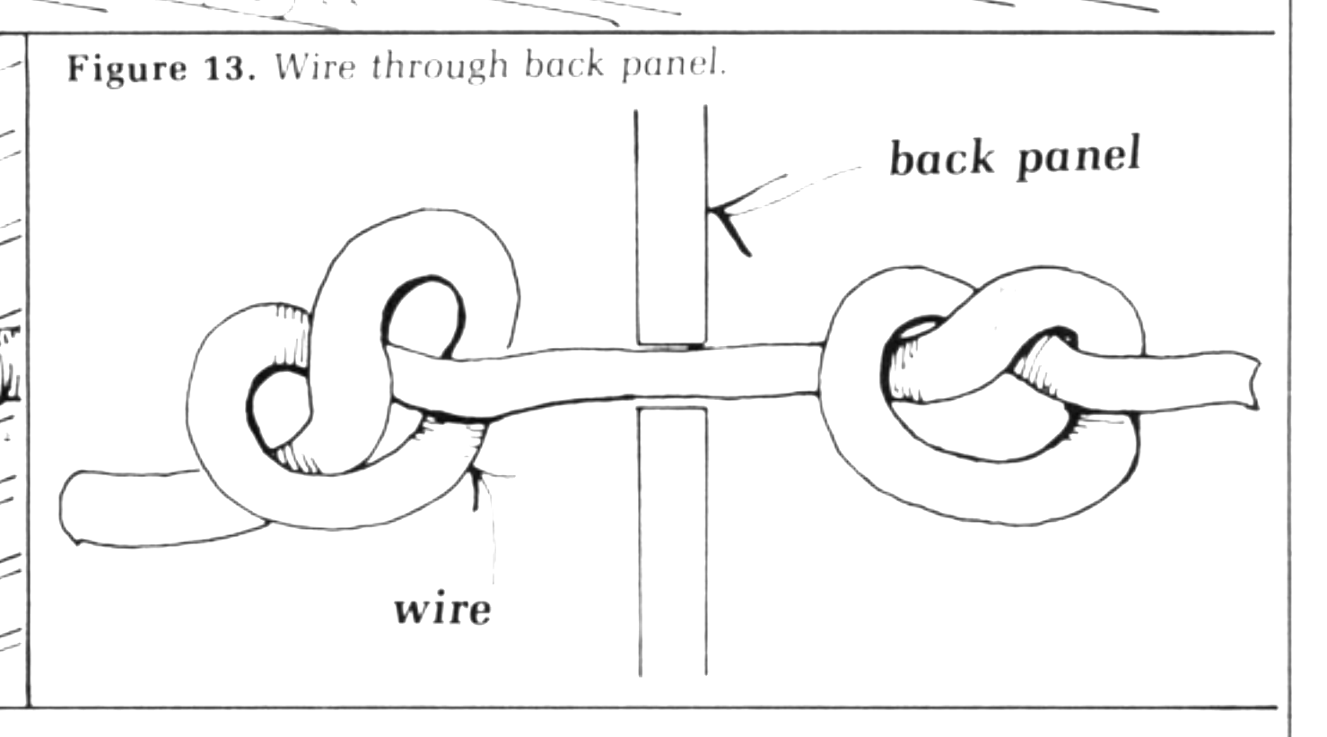
To prevent putting any strain on the connectors by the wires leaving the box through the slots in the back panel, tie a knot in each lead before and after it goes through the slot — see Figure 13— making sure that there is slack on the inside of the box.
Nothing could be easier to operate. Attach the 16-pin DIL jumper cable between SK1 and the Latch Card or some other 8-bit output port, making sure that the orientation of the plugs is correct. If some other 8-bit output port is used, you must make sure that the various signals and power lines have been transposed to suit SK1.
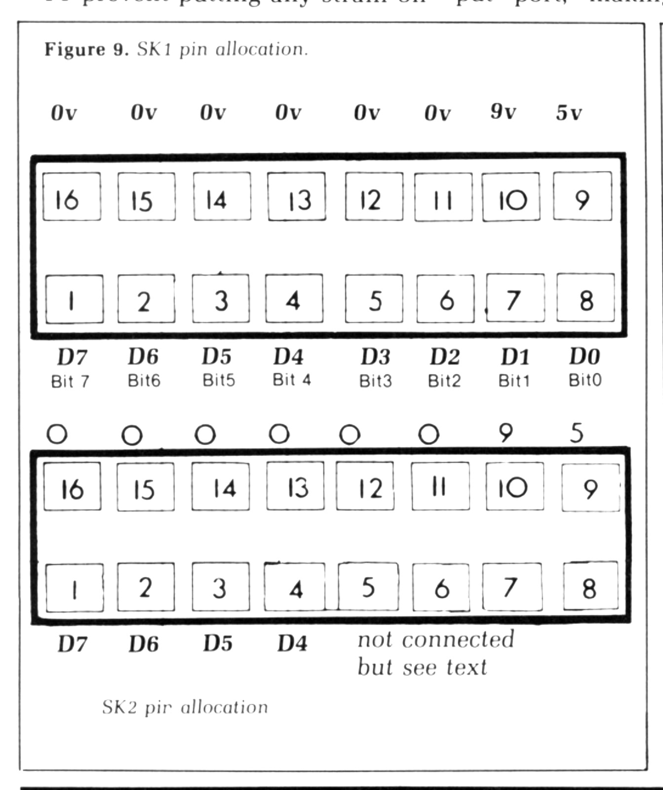
Writing zero to the port will turn off all the loads and writing a 1 to any of the low-order data bits will turn on that particular relay, e.g. POKE the port with 1 will turn on relay 1, POKE with 2 will turn on relay 2, POKE with 3 and both relay 1 and 2 will be turned on.
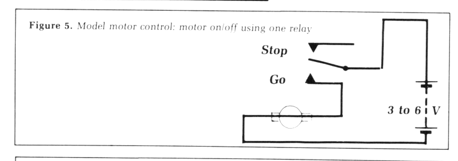
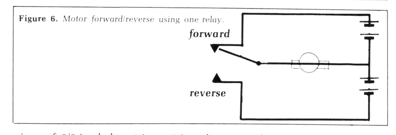
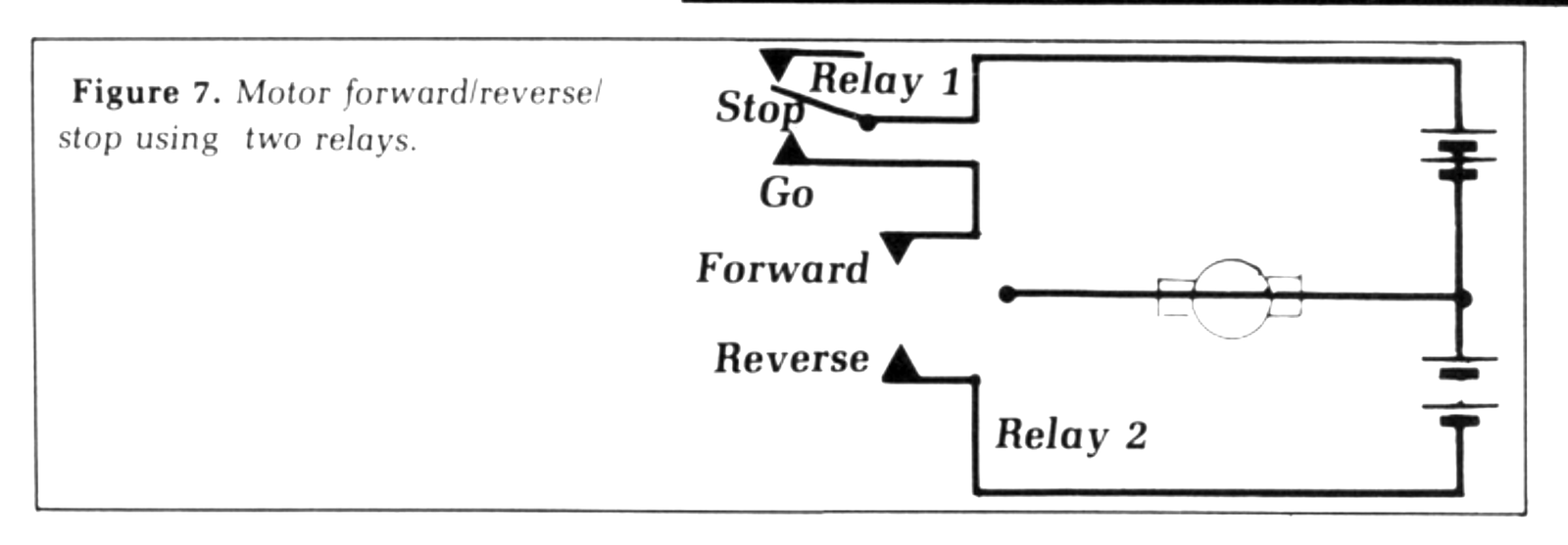
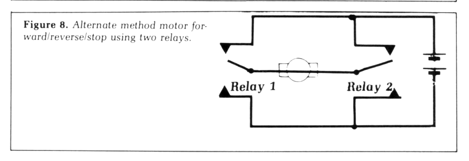
The Power Card will control small DC model motors easily but when that is being done the Power Card must not be connected to the mains. Figure 14 gives details.
Here is a sample program to drive Power Card using your computer and the Latch Card or interface.
10 REM ASSIGN PORT ADDRESS TO P
20 LET P =36850
30 REM ASSIGN MAXIMUM PAUSE TIME TO T
40 LET T=100
50 REM RANDOMLY SWITCH EACH RELAY
60 REM AT RANDOM TIMES
70 POKE P,RND*15
80 PAUSE1 + T*RND
90 GOTO 70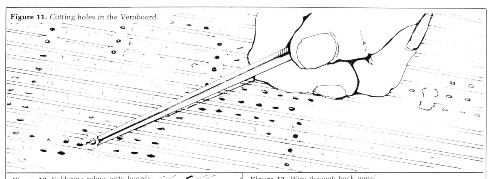
Note: Type-in program listings on this website use ZMAKEBAS notation for graphics characters.