
This program renders a wireframe 3D cube on screen using a full 3×3 rotation matrix combined with scaling and translation transforms. The shape is defined by 8 vertices and 12 edges stored in DATA statements, with rotation angles set to 40°, 20°, and 50° around the X, Y, and Z axes respectively. The transformation matrix (subroutine 720) is itself stored as DATA expressions using trigonometric functions, which are read with RESTORE and evaluated at runtime. Rather than using DRAW for edges, the program manually steps along each edge in unit increments using direction cosines, plotting individual points and clipping against screen boundaries. A centroid-finding routine (line 1000) computes the geometric center of the shape to serve as the pivot point for the rotation.
Program Structure
The program is organized into a main control sequence (lines 10–240) that calls a series of subroutines in order, plus a border-drawing routine at line 250. Execution flows as follows:
- Display introduction text and wait for a keypress (lines 20–40)
- Draw a screen border (line 250 subroutine)
- Initialize the shape data — vertices and edges — from DATA (line 260 subroutine)
- Find the centroid of the shape (line 1000 subroutine)
- Build the 4×4 transformation matrix from trig DATA (line 720 subroutine)
- Apply the combined rotation/scale/translation to each vertex (line 900 subroutine)
- Draw the transformed edges (line 460 subroutine)
- STOP
Shape Definition
The cube is stored as two parallel arrays: s(3,np) holds the X, Y, Z coordinates of np=8 vertices, and e(ne,2) holds the vertex-index pairs for ne=12 edges. Coordinate values range from 0 to 200 in each axis, forming a 200-unit cube. The DATA at lines 390–440 encodes these values; lines 420–440 list edge connectivity pairs such as 1,2 (vertex 1 to vertex 2).
Transformation Matrix Construction
The rotation matrix is stored as DATA expressions at lines 730–810, using COS and SIN of the pre-calculated angles rx, ry, rz. These are read into the 4×4 array a(4,4) via RESTORE 720 at line 820. The loop uses SGN PI (which evaluates to 1) as the loop start value — a slightly indirect way to write FOR e=1 TO 4.
The combined scaling and translation matrix b(4,4) is then built at lines 840–890 by reading another DATA block (line 870) that multiplies rows of a by scale factors sx, sy, sz and appends translation values tx, ty, tz. Notably, the DATA at line 870 is embedded inline within the loop rather than placed at a separate location, relying on RESTORE 850 to position the DATA pointer correctly at the start of the subroutine entry.
Translation/Rotation Application
Subroutine 900 applies the combined matrix b to each vertex. Each vertex is first offset relative to the centroid (xc, yc, zc), matrix-multiplied, and then the centroid is added back. This ensures rotation occurs about the shape’s geometric center rather than the origin. Results are stored in m(3,np); only the X (m(1,q)) and Y (m(2,q)) components are used for 2D screen plotting — no explicit perspective divide is performed, making this an orthographic projection.
Edge Drawing Routine
Rather than using the built-in DRAW command, subroutine 460 manually steps along each edge. For each edge, it computes direction cosines lx and ly by dividing the delta components by the Euclidean distance r, then iterates from 0 to r in steps of ds=1, computing and PLOTting each point. Screen boundary clipping is performed inline at lines 640–670, checking that each point lies within 0–255 (X) and 0–175 (Y) before plotting.
A check at line 500 skips any edge whose first vertex index is 0 (IF v1=0 THEN GO TO 700), providing a mechanism to encode “pen up” moves, though no such entries exist in the current DATA.
Notable Techniques and Anomalies
- Storing trigonometric expressions directly as DATA (lines 730–810) is an unusual technique; the BASIC interpreter evaluates these expressions when they are READ at runtime.
- The
SGN PIidiom at line 820 evaluates to 1 and is used as the loop lower bound — functionally equivalent toFOR e=1but more circuitous. - Variables
p,q, andrare reused in subroutine 1000 (centroid calculation) and also in subroutine 460 (edge drawing), which would cause a conflict if both were active simultaneously — but since they are called sequentially, no actual collision occurs at runtime. - Similarly, the loop variable
eis used both as the edge-index loop variable (lines 350, 470) and as a matrix row index (line 820, 850), which works only because BASIC reuses the same variable name in separate loop contexts. - The scaling matrix construction at line 870 repeats each scale factor three times (e.g.,
sx*a(i,1), sx*a(i,1), sx*a(i,1)) — this applies the same scale to all three columns of each row, effectively makingsx=sy=szregardless of their individual values set at lines 90–110. - No perspective projection is applied; the result is a parallel (orthographic) projection onto the XY plane.
Variable Summary
| Variable | Purpose |
|---|---|
sx, sy, sz | Scale factors (all set to 0.3) |
tx, ty, tz | Translation offsets (all set to 1) |
rx, ry, rz | Rotation angles in radians (40°, 20°, 50°) |
np, ne | Number of points (8) and edges (12) |
s(3,np) | Original vertex coordinates |
e(ne,2) | Edge vertex-index pairs |
m(3,np) | Transformed vertex coordinates |
a(4,4) | Rotation matrix |
b(4,4) | Combined scale/translate/rotation matrix |
xc, yc, zc | Centroid coordinates |
Content
Image Gallery
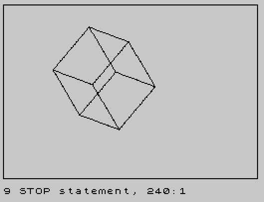
Source Code
   10 REM 3D drawing
   20 PRINT "This program is an example of   how this computer can be pro-   grammed to draw a 3-D shape.    Press any key to see demo and   then study the program.Origin-  ally printed in Nick Hampshire's""Color Graphics""."
   30 IF INKEY$="" THEN GO TO 30
   40 CLS
   50 GO SUB 250
   60 REM set up constant variables & arrays
   70 DIM a(4,4)
   80 DIM b(4,4)
   90 LET sx=.3
  100 LET sy=sx
  110 LET sz=sx
  120 LET tx=1
  130 LET ty=tx
  140 LET tz=tx
  150 LET rx=40* PI/180
  160 LET ry=20* PI/180
  170 LET rz=50* PI/180
  180 REM main loop
  190 GO SUB 260
  200 GO SUB 1000
  210 GO SUB 720
  220 GO SUB 900
  230 GO SUB 460
  240 STOP
  250 PLOT 0,0:DRAW 255,0:DRAW 0,175:DRAW -255,0:DRAW 0,-175:RETURN
  260 REM initialize shape
  270 LET np=8
  280 LET ne=12
  290 DIM s(3,np)
  300 DIM e(ne,2)
  310 DIM m(3,np)
  320 FOR n=1 TO np
  330 READ s(1,n),s(2,n),s(3,n)
  340 NEXT n
  350 FOR e=1 TO ne
  360 READ e(e,1),e(e,2)
  370 NEXT e
  380 REM x,y,z POINT coor
  390 DATA 0,0,200,200,0,200,200,0,0,0,0,0
  400 DATA 0,200,200,200,200,200,200,200,0,0,200,0
  410 REM connectionDATA
  420 DATA 1,2,2,3,3,4,4,1
  430 DATA 5,1,2,6,4,8,7,3
  440 DATA 6,5,5,8,8,7,7,6
  450 RETURN
  460 REM  DRAW
  470 FOR e=1  TO ne
  480 LET v1=e(e,1)
  490 LET v2=e(e,2)
  500 IF v1=0 THEN GO TO 700
  510 LET xb=m(1,v1)
  520 LET yb=m(2,v1)
  530 LET xe=m(1,v2)
  540 LET ye=m(2,v2)
  550 LET ds=1
  560 LET p=xe-xb
  570 LET q=ye-yb
  580 LET r= SQR (p*p+q*q)
  590 LET lx=p/r
  600 LET ly=q/r
  610 FOR i=0 TO r STEP ds
  620 LET x=xb+i*lx
  630 LET y=yb+i*ly
  640 IF x>255 THEN GO TO 690
  650 IF y>175 THEN GO TO 690
  660 IF x<0 THEN GO TO 690
  670 IF y<0 THEN GO TO 690
  680 PLOT x,y
  690 NEXT i
  700 NEXT e
  710 RETURN
  720 REM transformational matrix
  730 DATA COS (ry)* COS (rz)
  740 DATA COS (ry)* SIN (rz)
  750 DATA - SIN (ry),0
  760 DATA COS (rx)*(- SIN (rz))+ SIN (rx)* SIN (ry)* COS (rz)
  770 DATA COS (rx)* COS (rz)+ SIN (ry)* SIN (rz)
  780 DATA SIN (rx)* COS (ry),0
  790 DATA (- SIN (rx))*(- SIN (rz))+ COS (rx)* SIN (ry)* COS (rz)
  800 DATA - SIN (rx)* COS (rz)+ COS (rz)* SIN (ry)* SIN (rz)
  810 DATA COS (rx)* COS (ry),0,0,0,0,1
  820 RESTORE 720:FOR e= SGN PI TO 4:FOR n= SGN PI TO 4:READ a(e,n):NEXT n:NEXT e
  830 REM scaling and transtation matrix
  840 RESTORE 850
  850 FOR i=1 TO 4:FOR e=1 TO 3
  860 READ b(i,e)
  870 DATA sx*a(i,e),sx*a(i,e),sx*a(i,e),sy*a(i,e),sy*a(i,e),sy*a(i,e),sz*a(i,e),sz*a(i,e),sz*a(i,e),tx,ty,tz
  880 NEXT e:NEXT i
  890 RETURN
  900 REM perform translation
  910 FOR q=1 TO np
  920 LET xt=s(1,q)-xc
  930 LET yt=s(2,q)-yc
  940 LET zt=s(3,q)-zc
  950 LET m(1,q)=xc+(xt*b(1,1)+yt*b(2,1)+zt*b(3,1)+b(4,1))
  960 LET m(2,q)=yc+(xt*b(1,2)+yt*b(2,2)+zt*b(3,2)+b(4,2))
  970 LET m(3,q)=zc+(xt*b(1,3)+yt*b(2,3)+zt*b(3,3)+b(4,3))
  980 NEXT q
  990 RETURN
 1000 REM find centroid
 1010 LET p=0:LET q=p:LET r=p
 1020 FOR i=1 TO np
 1030 LET p=p+s(1,i)
 1040 LET q=q+s(2,i)
 1050 LET r=r+s(3,i)
 1060 NEXT i
 1070 LET xc=p/np
 1080 LET yc=q/np
 1090 LET zc=r/np
 1100 RETURN
 1110 SAVE "3D DRAW" LINE 10
Note: Type-in program listings on this website use ZMAKEBAS notation for graphics characters.