
Chapter One: The Microcomputer
1.1 Introduction
A computer based on the Z-80 operates in the same manner as any other machine be it micro, mini or mainframe. Before we can discuss the Z-80 and its use in any detail, it is first necessary to describe the operation of a typical microcomputer. This will serve to define the terms used in the rest of the book, and place the Z-80 in its role as the central processor of a powerful, but conventional computer.
1.2 Computer Architecture
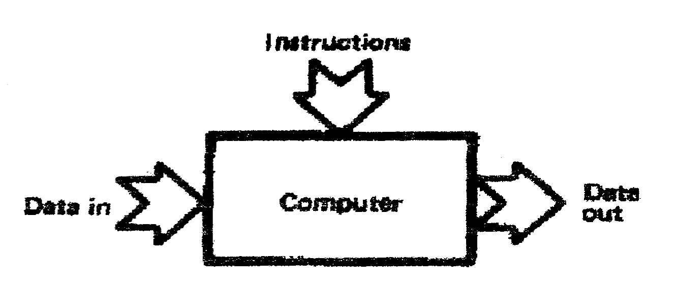
All computers can be represented by the block diagram of Fig.1.1, and can be considered as manipulators of data. The actual form of the data will depend on the application. In commercial computing the data will be VAT returns, sales figures, bank accounts and similar information. In industrial control, the data will be plant sensors and actuators. In a computer game the data will be the players hand controls and the video display. The data can be split into input data, which is to be processed, and the output data, which is the result of the processing. To produce the output data, the computer follows a set of procedures, called instructions, which define the operations that are to be performed on the input data.
The computer can be represented in more detail by Fig.1.2, and can be considered to consist of three basic units, a store, an input/output unit and a central processor unit, all interconnected by a common highway. The input and output unit obviously receives and transmits data from and to the outside world.
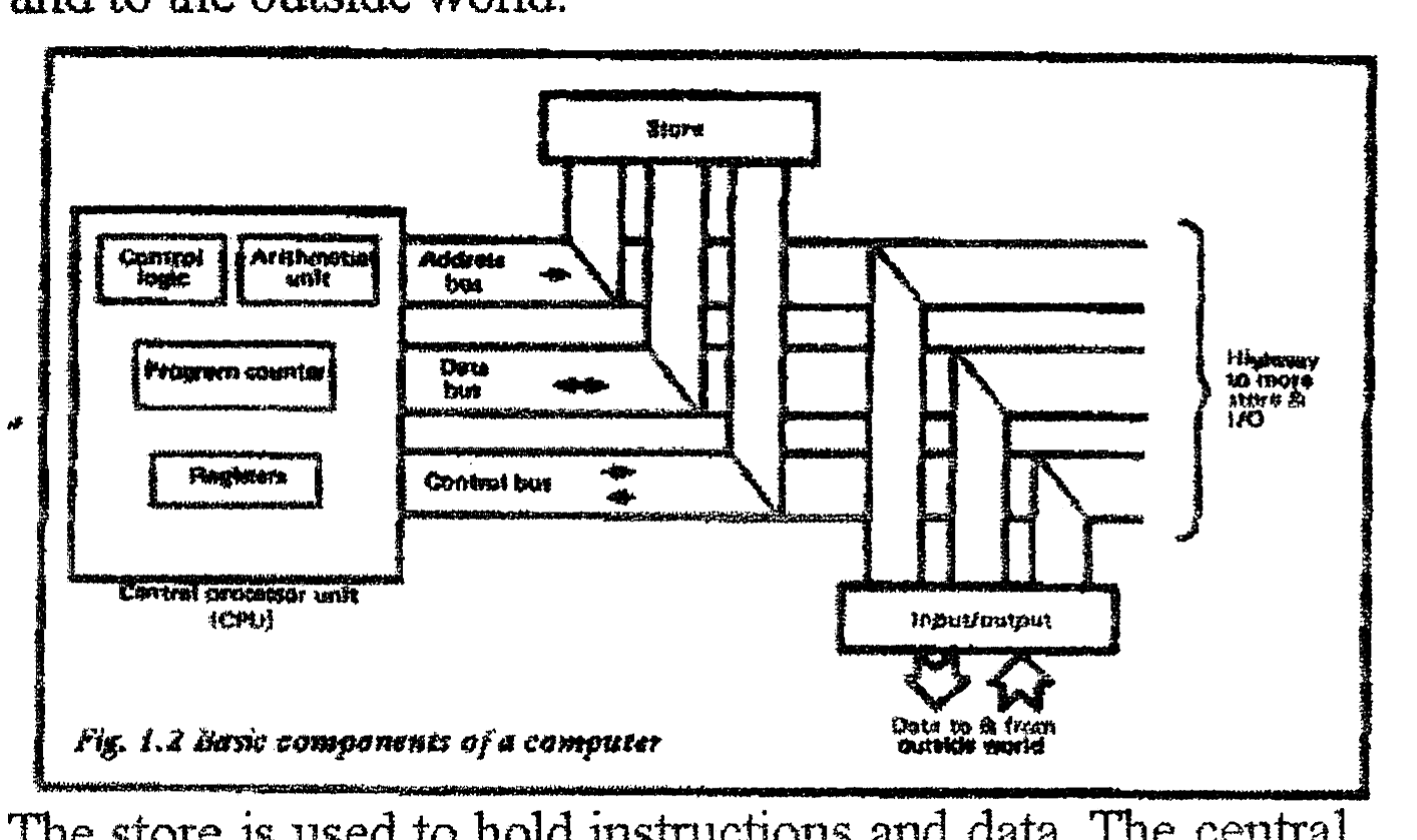
The store is used to hold instructions and data. The central processor unit controls the operation of the machine, and performs the logic and arithmetic operations required by the instructions.
The store is used to hold the instructions and temporary data in the form of numbers. It can best be considered as an array of pigeon holes, each of which can hold one number called (rather confusingly) a Word. Each pigeon hole is known as a store location, and has a unique address (similar to a house address) by which it can be identified. We can thus say, for example, “store location 3220 contains 127”. This means that the pigeon hole whose address is 3220 has the number 127 stored in it.
A typical microcomputer will have over 16000 store locations (although small machines may have less than 1000). All common microprocessors deal basically with 8 bit numbers, often called Bytes. The numbers stored will therefore be in the range 0 to 255. As will be seen later, this is not the restriction that it might at first appear.
1.3 The Store
The store is used to hold the instructions and temporary data in the form of numbers. It can best be considered as an array of pigeon holes, each of which can hold one number called (rather confusingly) a Word. Each pigeon hole is known as a store location, and has a unique address (similar to a house address) by which it can be identified. We can thus say, for example, “store location 3220 contains 127”. This means that the pigeon hole whose address is 3220 has the number 127 stored in it.
A typical microcomputer will have over 16000 store locations (although small machines may have less than 1000). All common microprocessors deal basically with 8 bit numbers, often called Bytes. The numbers stored will therefore be in the range 0 to 255. As will be seen later, this is not the restriction that it might at first appear.
The store does not differentiate between instructions and data; both are held in exactly the same form. The central processor unit determines whether the number in a particular store location is considered to be an instruction or data.
The store connects to the rest of the computer in a manner similar to Fig.1.3. The three groups of signals are known as the address bus, the data bus and the control bus. (The term bus is short for busbar, sometimes the term highway is used.)
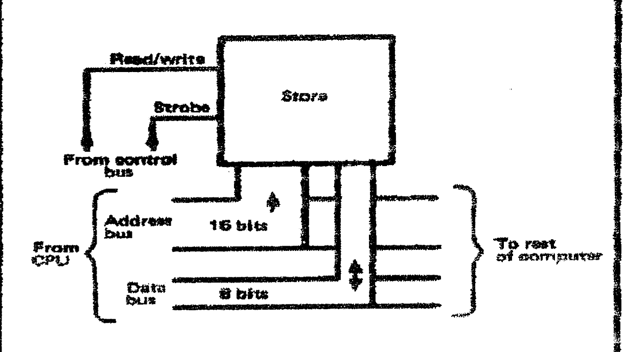
The address bus is used by the central processor to identify which store address is to be accessed. Usually, up to 65,536 (called 64K) locations can be used with a microprocessor, necessitating a 16 bit address bus.
The data bus is used to transfer data and instruction between the store and the central processor unit. Movement can take place from store to CPU, or CPU to store, so the data bus is bi-directional. All common microprocessors use an 8 bit data bus.
The control bus contains the timing signals to sequence the movement of data or instructions. In the majority of systems there are basically two signals. A read/write line is used to indicate if a number is to be loaded into or read from, the addressed location, and a strobe signal indicates when the number on the data bus is valid We. the transients due to different propagation delays, reflections etc. have died away). Different microprocessors use slightly different signals.
Fig.1.4a summarizes the signals used to write a store location, and Fig. 1.4b the signals used to read from a store location.
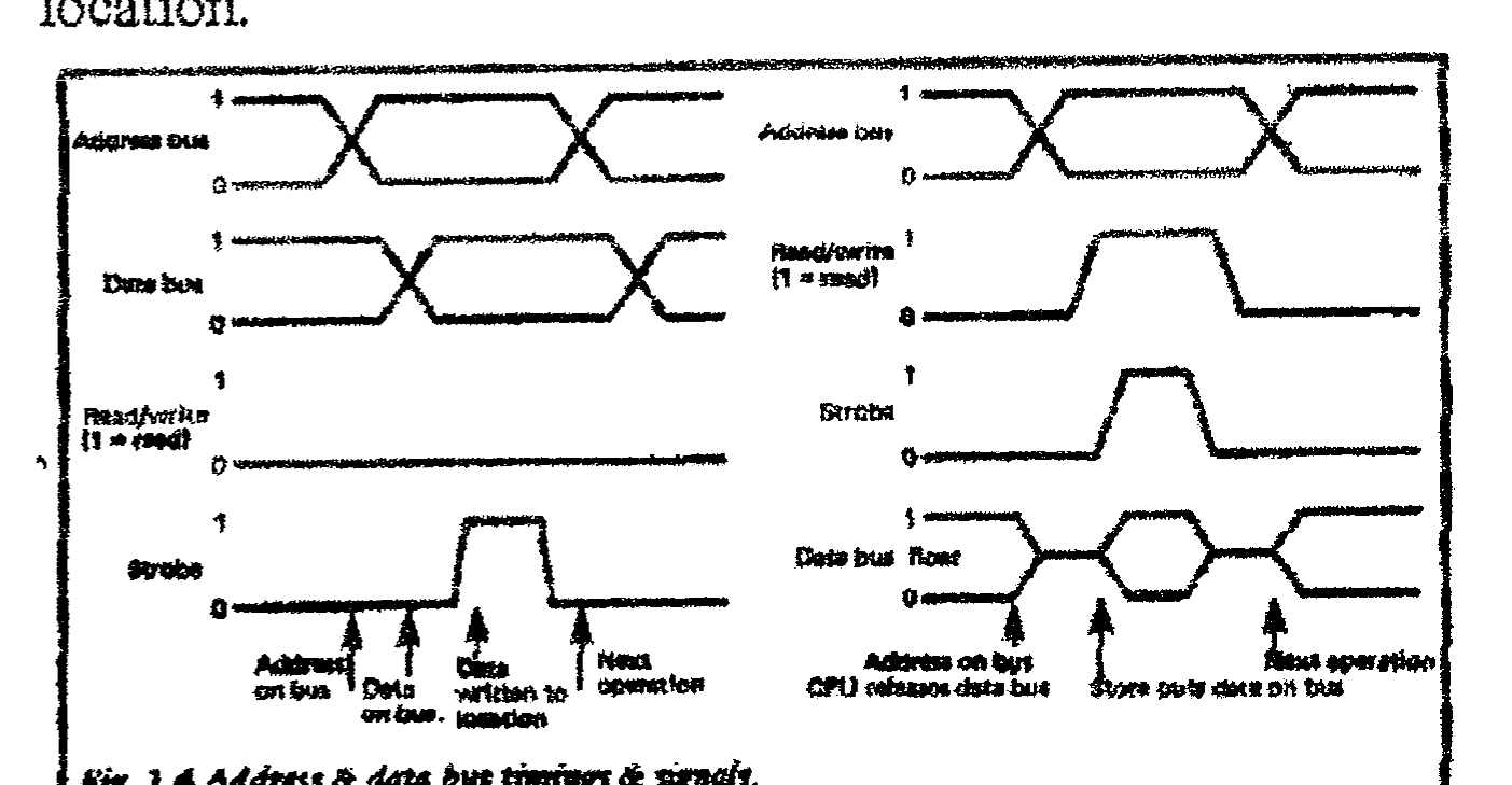
When a number is written to a store location, the previous contents are obviously overwritten. When a number is read from a store location, the store location contents are unaltered; the number put onto the data bus is merely a COPY of the store contents.
The store in Fig.1.3 is known as a RAM or Random Access Memory. This is a term that causes some confusion, but simply means that each store location can be accessed in exactly the same time. Bulk storage devices, such as tapes and discs, have a variable access time which depends on where the information is stored and where the tape or disc currently is when the information is needed.
Another form of storage commonly encountered is a ROM, for Read Only Memory. This is a conventional store whose contents are fixed and cannot be altered by the computer. Usually a ROM is used to hold a fixed program (such as the BASIC interpreter or an Assembler as described later). To the central processor, a ROM behaves in exactly the same manner as the rest of the store.
1.4 The Central Processor Unit (or CPU)
The computer follows instructions held in the store (in the form of numbers). Normally, instructions are held in sequential store locations. To obey an instruction we must go through the following steps:
- i. Address the store to get the next instruction.
- ii. Decode the instruction to decide what needs to be done
- iii. Obey the instruction. This will usually involve the store again to read, or write, data and will often require simple arithmetic operations.
- iv. Decide where the next instruction is held in the store, and go back to step 1.
Most instructions therefore require two operations on the store; the first to read the instruction, the second to read the data to be used or write a result back to the store. Sometimes the operations above are referred to as three steps :
- Fetch cycle (instruction is fetched, steps i and ii)
- Execute cycle (instruction is obeyed, step iii)
- Reset cycle (the internal logic is reset for the next instruction, step iv)
The FER sequence has been called the heartbeat of a computer.
The component parts of a central processor unit are shown on Fig.1.5. For simplification, internal connections are omitted.
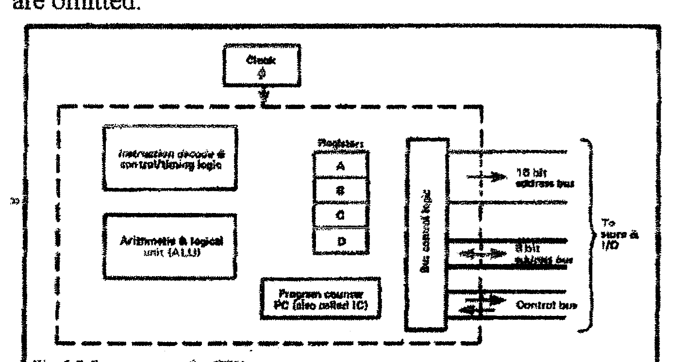
The program counter (PC, also known as an instruction counter, IC) holds the address of the current instruction. Because most microcomputers can address up to 64K, the PC will usually be a 16 bit register. With the exception of JUMP instructions (the machine code equivalent of a BASIC GOTO instruction), the program will be held in sequential store locations. This means that the PC can literally be a counter which is pulsed by the control logic at step iv above.
In addition to the storage provided by the RAM, fast storage (for temporary scribbling pad purposes) is provided by registers in the CPU. These can hold one number to the same word length as the store (8 bits for all common micros). Some microprocessors (such as the 6502) have only one register, whereas some (such as the Z-80) have as many as sixteen. Fig.1.5 shows four registers for illustrative purposes. The use of registers will be described later.
Associated with the registers is the Arithmetic and Logic Unit (or ALU). There are actually very few machine code instructions; as we shall see later, most are variations on:
- Fetch a number from a store location (or input port) to a register.
- Write a number to a store location (or output port) from a register.
- Add (or subtract) a number from a store location to a register, result to a register.
The ALU performs the arithmetical operations (and some logical operations such as AND, OR) required by the instructions.
Finally, we have the block labeled control/timing logic. This contains the logic to decode the instructions and sequence the steps i to iv above. This involves selecting routes between the store, the ALU, the registers and the highways. The control/timing logic is usually the most complex part of a computer.
Associated with the control logic is a simple clock oscillator which provides the basic timing pulses. Usually this is a crystal oscillator in the range I to 4 MHz.
A microprocessor is often thought of as a computer, but is, in fact, simply the CPU of a computer. A microprocessor contains the elements of Fig 1.5, but needs external RAM/ROM and Input/Output equipment to be useful.
1.5 Input And Output
A computer connects to a variety of I/O equipment, printers, keyboards, VDUs, cassette recorders etc. These connect to the computer highway as shown on Fig.1.6. Each 1/0 device is identified by an address. I/O addresses are commonly known as ‘Ports’, so we could have, say, a printer connected to Port 3 and a keyboard to Port 5.
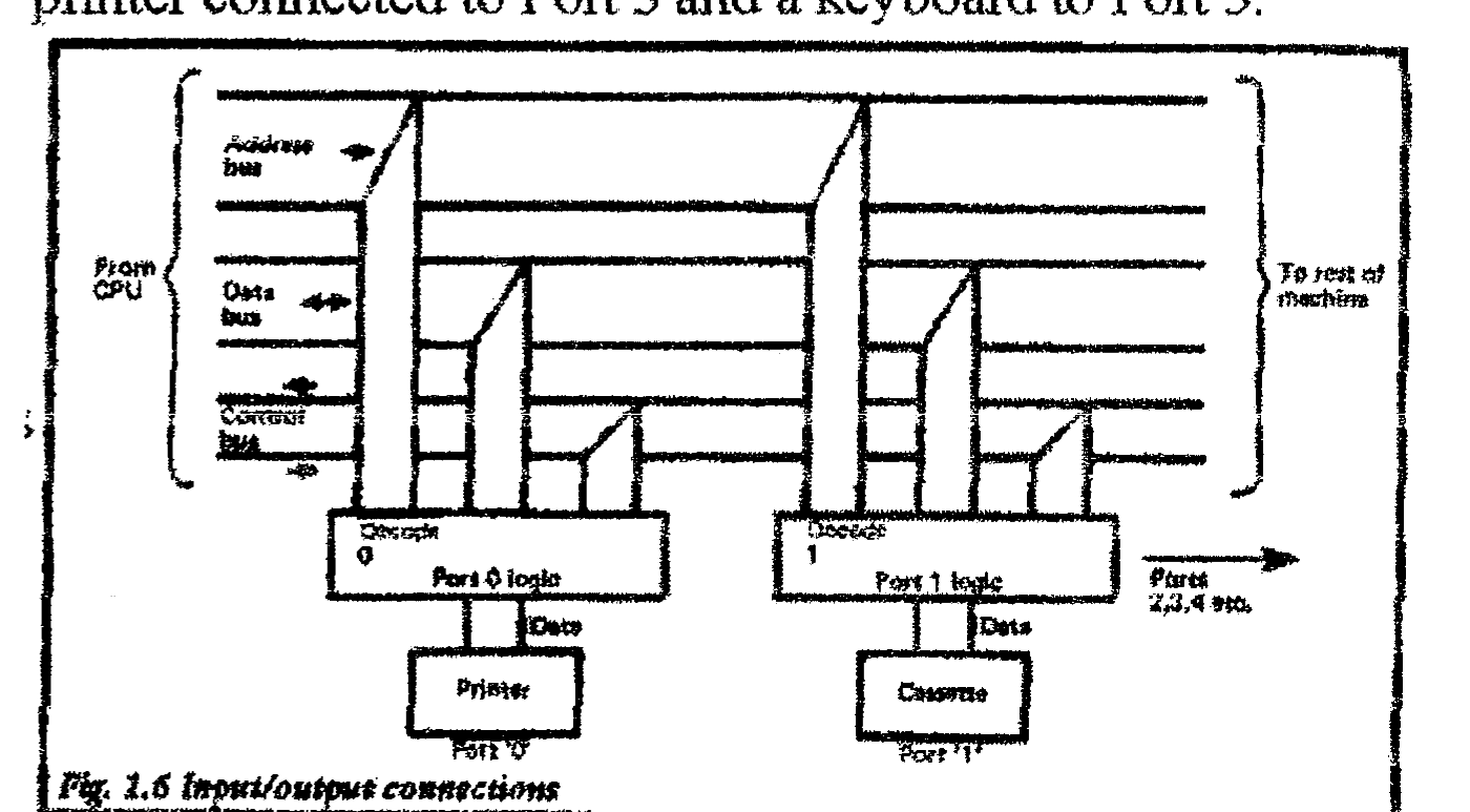
Data is transferred to and from an 1/0 port via the highway. The port address is placed on the address highway, the read/write control line used to identify the direction of the transfer, and the I/O control line used to signify that the address is a port address, not a store address. Data transfer then takes place via the data highway. Some microprocessors (such as the 6800) do not have an I/O control line and literally deal with I/O addresses in the same ways and with the same instructions, as store addresses. With these microprocessors a store and a port cannot have the same address.
Most microprocessors allow data to be transferred between I/O ports and registers or between I/O ports and store locations we shall discuss later the techniques used to resolve the vast difference in speed between slow speed devices (such as printers) and the computer itself.
1.6 Instructions And Programs
As anyone who has written a program in BASIC will know, a computer simply obeys a sequence of instructions called a program. In a high level language such as BASIC or PASCAL, these instructions are written in ‘English’. A computer actually obeys instructions represented by numbers called a machine code program. When a high level program is obeyed, a special program built into the computer (called a compiler or an interpreter) converts the high level language program to an equivalent machine code program. This action is invisible to the high level language user.
A machine code instruction must specify:
- i. What is to be done (e.g. Add, fetch data, store data, etc.)
- ii. Where the data is to be found, and where the result is to be placed (e.g. “Fetch the data from store location 2000 to Register B”, or “Add the data in store location 1575 to the data in Register A putting the result in Register A”).
In following chapters we will see how these ideas are actually specified given the limitations of an 8 bit word. There are actually a very limited set of instructions in a computer, and most are variations on:
1.6.1 Fetch
“Fetch data from a specified store location (or register) to a specified register”.
1.6.2 Store
“Store data from a specified register to a specified store location”. Sometimes Fetch and Store are collectively called “Moves” or “Loads”.
1.6.3 Add
“Add data from a specified store location (or register) to the data in another specified store location (or register) the result to go to a specified store location (or register)”.
Usually Adds take the simpler form, “Add data from a specified store location to the data in register A, the result to go to Register A”.
1.6.4 Subtract
As 1.6.3 but subtraction is performed. Note that multiplication and division are not available on any common microprocessor.
1.6.5 Logical
As 1.6.3, but logical operations such as AND, OR, NEV are performed between the data.
1.6.6 Shifts
Data in a microprocessor is held as 8 bit binary numbers. A shift instruction moves the data in a register up, or down by one place. If we have the bit pattern 10110101, a simple shift up would produce 01101010, and simple shift down would produce 01011010. A shift up multiplies a number by two, a shift down divides by two. As will be seen later, there are many variations on the shift instruction.
1.6.7 lumps
Normally, instructions are held in sequential store locations. A Jump instruction is the machine code equivalent of the BASIC GOTO, and specifies where the next instruction is to be found (e.g. Jump to location 3220).
1.6.8 Conditional lump
A conditional jump tests the condition of a register, the results of which determine if a jump instruction is to be obeyed (e.g. Jump to 4057 if register A is zero). This is the machine code equivalent to the BASIC IF condition THEN GOTO (line number).
1.6.9 Subroutine Call and Return
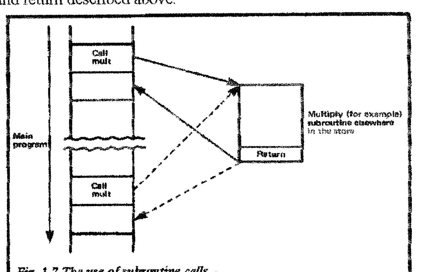
Programmers in BASIC will be familiar with the concept of a subroutine with the GOSUB and RETURN instructions. A subroutine allows a piece of program that is used frequently to be written once and called when needed by the rest of the program. This is best shown by Fig.1.7. Machine code subroutine calls work in exactly the same way. A subroutine call acts like a jump to the start of the subroutine (e.g. Call 7087 would take us to the subroutine starting at location 7087). A Return instruction is placed at the end of the subroutine, to take us back to the location in the main program immediately after the subroutine call. Subroutines can call subroutines (called Nesting). A Binary to BCD subroutine, for example, would need to use multiplication and division subroutines. In most microprocessors, conditional subroutine calls, and conditional returns are provided as well as the simple call and return described above.
1.6.10 Input/Output Instructions
Input/output instructions must specify the I/O port address, the direction (in or out) and the source (or destination) of the data (i.e. which register or which store location).
1.6.11 Control Instructions
Most microprocessors have a small number of control instructions such as STOP, Disable Interrupts and similar operations. These do not involve data.
At first sight, the vast array of instructions available on a microprocessor can be rather awe inspiring (the Z-80 has 158 different instruction types). Much of the inevitable feeling of confusion can be assuaged by remembering that most instructions are simple variations of the ten types outlined above.
1.7 Why Machine Code?
Programming in BASIC is simple and straightforward, so it is not unreasonable to ask why one should bother with the trials, tribulations and complexity of machine code programming. There are really three reasons.
The first is that it is possible to perform operations in machine code that are impossible (or difficult) to achieve in BASIC. Control of external items like a model railway would be difficult in simple BASIC for example.
The second reason concerns speed. BASIC is notoriously slow, and is quite unsuited to, say dynamic video games. Machine code programs operate many times faster than BASIC programs.
The final and most compelling, reason is that machine code programming is an intellectual challenge akin to chess or bridge. The mental exercise of programming (in any form) is very addictive and this is particularly true of machine code programs.
1.8 Machine Code And Assemblers
The instructions a computer actually obeys are held in the form of binary numbers. To assist human beings to read these numbers, it is usual to express them in Hex, so 1010 0111 becomes A7 (see Appendix A).
A machine code program therefore looks something like:
F5 C5 D6 64 3E Z0 D3 00 etc.which is still fairly incomprehensible.
It is easier to follow a machine code program if simple mnemonics are used to represent the instructions. The actual mnemonics used on the Z-80 will be described later, but in general they are simple to understand. A program written in mnemonics is said to be written in Assembler Language, and looks more understandable.
LD A, 33
INC HL
JP NZ, LOOP
Each of these corresponds directly to a single machine code instruction, LD A,33 for example, means put the number 33 into register A.
The program written in Assembler Mnemonics is converted to machine code by a program called (surprise, surprise) an Assembler. The Assembler has editing facilities similar to those found in BASIC and makes machine code programming much less infuriating. In later chapters, examples of Assembler programs will be given. Assemblers are not usually provided with computers, and have to be purchased separately.
1.9 Further Reading
The description of computer architecture in this chapter has, of necessity, been rather brief. More detailed discussions can be found in the following books also published by Bernard Babani (publishing) Ltd:
Book No. BP72 – A Microprocessor Primer
Book No. BP78 – Practical Computer Experiments
Book No. BP66 – Beginners Guide to Microprocessors
Book No. BP77—Elements of Electronics – Book 4
Microprocessing Systems and Circuits.