REVERSE VIDEO
It is possible to directly invert the video signal that leaves the ZX80 and drives your TV. This is done by accessing pin 9/IC9, instead of pin 7/IC9, as the input (pin 4) to IC20. Below are the instructions for the modifications.
Remove the entire case from the ZX80. In the right center section of the back of the PCB you will see an etching that looks like this:
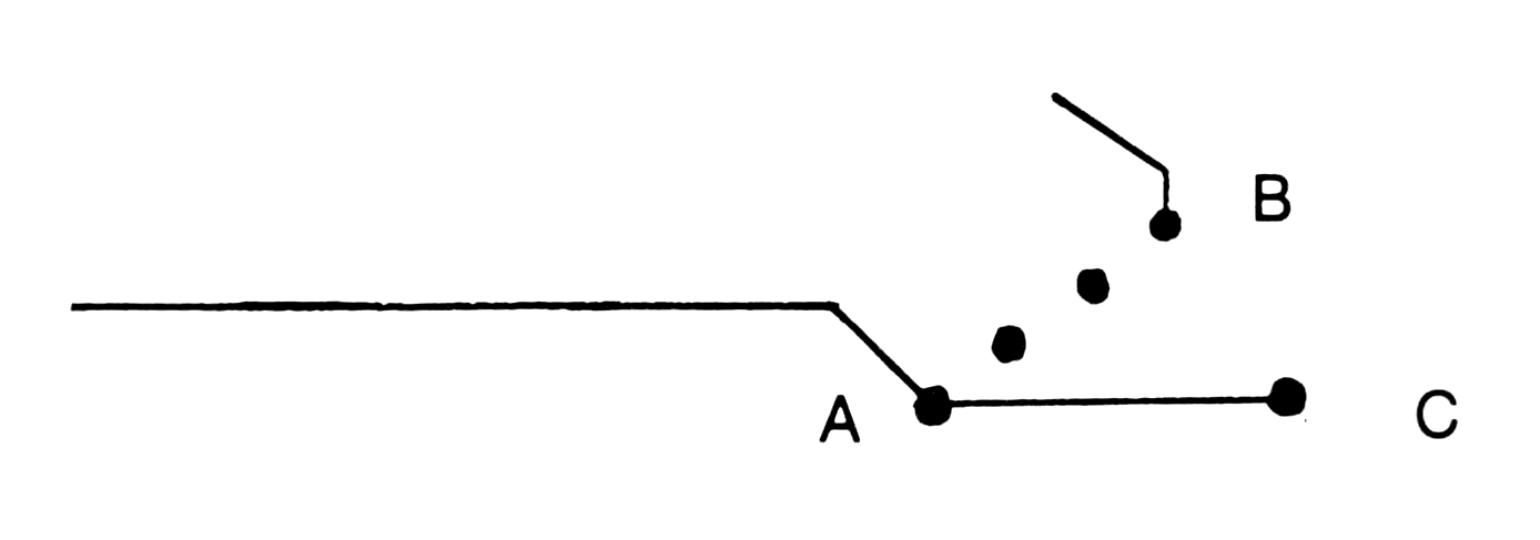
First, cut the trace between points A and C with a razor blade or exacto knife.
Now install the following circuit:
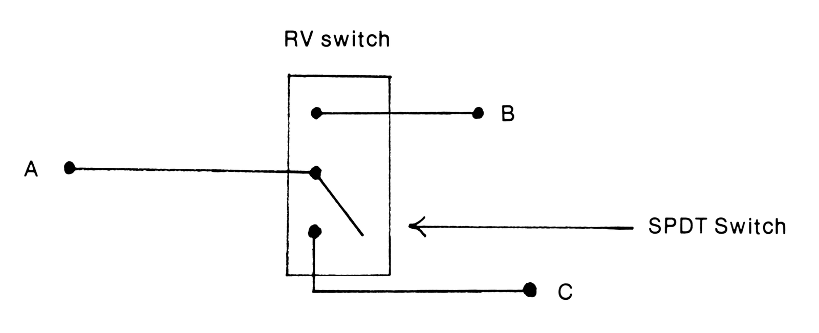
Drill an appropriately sized hole in the case. Mount the switch. Close up the case and power-up the system. You will notice that toggling the switch will cause the video to invert.
DIRECT VIDEO
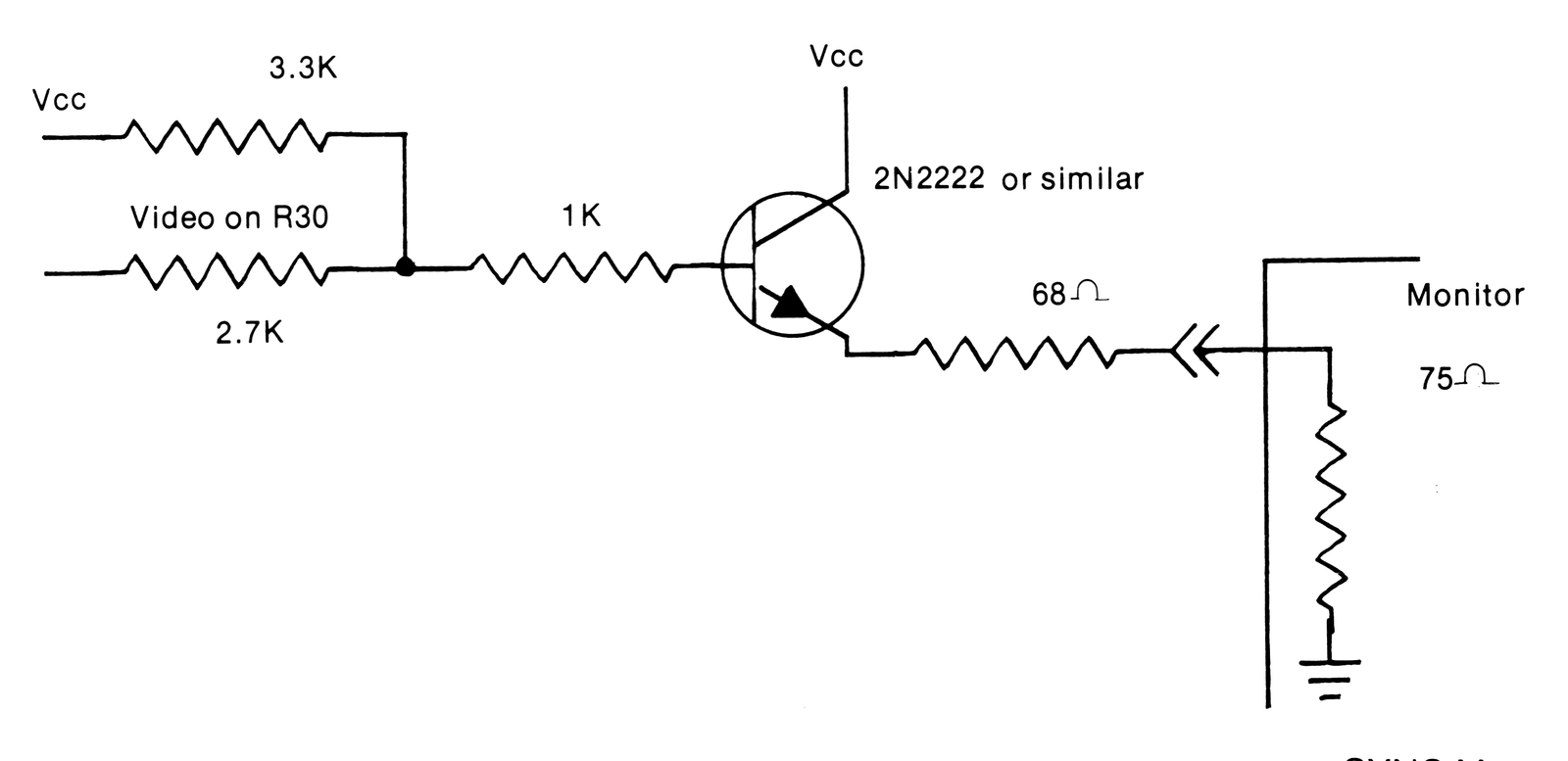
It is possible to connect a video monitor directly to the ZX80. This is accomplished by passing the RF modulator and adding a small amount of buffer circuitry. This circuit also reverses the video signal which can be controlled by the RV switch shown earlier.
Open the ZX80. Look at the modulator. (See Below.)
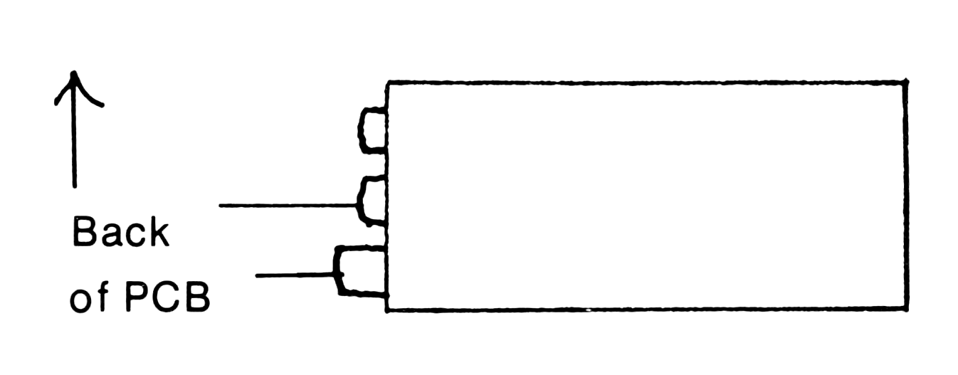
Tapping the video lead on R30 (see Schematic), you should run it through the buffer circuit shown below: