
Although the ZX80 has many fine features, some people complain about the small pads of the touch keyboard that comes with it. But this is not a serious problem. The ZX80 uses a matrixed keyboard, so you can easily add a bigger, parallel keyboard.
“Matrixed” means each key connects two wires, one for the key row, the other the key column. Sinclair’s matrix uses 8 rows and 5 columns which connect to 13 readily available points on the circuit board. Two pins descend from each key: When you depress the key, the pins make electrical contact, connecting an IC pin with the anode of a diode. This tells the computer which key you hit.
When you look for keyboards at electronic surplus houses, try to get these features:
- exchangeable key caps.
- molded block keyboards that come off circuit boards easily.
- caps with changeable legends.
- a circuit board matrix nearly matching the ZX80 matrix.
Unless you’re sure you can overcome the problems, avoid these keyboards:
- mechanical types.
- ASCII encoded.
- separate switches on PC board.
- Hall effect keys.
- brushes wiping printed contacts.
- capacitive keyboards.
Just wire your big matrixed keyboard in parallel with the existing one. Use standard single-pole, normally open keyswitches. Wire duplicate keys, such as “shift,” in parallel so both will function. If your big keyboard has a numeric pad, wire each switch in parallel with the number keys above the letter keys.
Use a continuous length of wire-wrap wire to daisy-chain one contact of each switch in each column. Do the same for the other switch contact in each row. Just push the insulation aside using the stripper of a wire-wrap tool.
All components are clearly labelled on the ZX80 board. You must wire both pins for each key. On the following chart, D3–D10 represent the anodes of the diodes on the front of the PC board. (Look for the diode symbol under the diodes. The anode is at the broad end of the triangle.) Looking at the top of IC10, the pin nearest the IC10 label is pin 1. Pin 16 is directly across from pin 1.
Connect your keyswitches as shown in the following diagram. As shown for key “1”, each key connects to the line below it and the line to its right. That is, wire key 1 to diode 6 and to pin 10 of IC10.
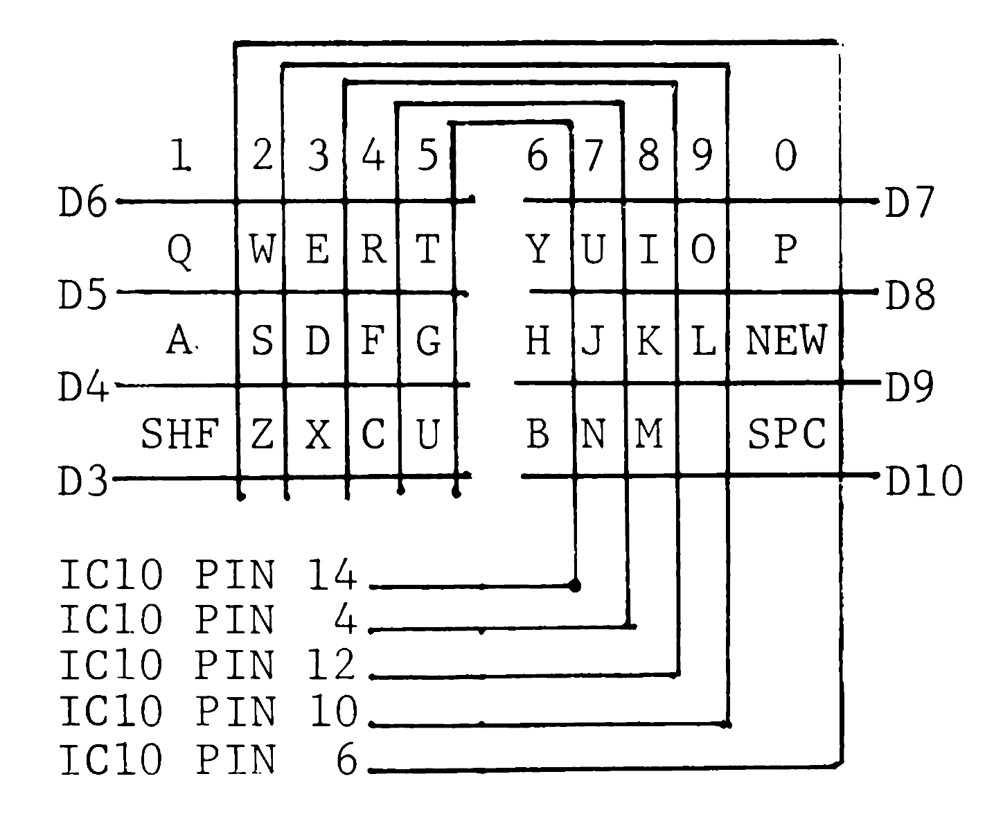
For quick removal, use eight spring-loaded test clips for diode connections and parallel IC10 with a 16-pin proto-clip. Ribbon cable makes a good-looking interconnect.
ANSWER TO CRYPTOQUOTE PUZZLE
“Who chooses to compete with machines accepts the conditions of slavery”–Norbert Weiner