
How Is It Done?
The ZX80 is supplied with a 4K ROM that contains the Basic interpreter. Therefore the average user will use the PRINT command of the Basic language to produce his pictures on the T.V. screen. However Basic is fairly slow.
For example the following Basic program draws a simple rectangular playing area, that could form part of many games, takes over 2 seconds to RUN.
10 FOR I=1 TO 32
20 PRINT "▒";        (shift A)    } Top line
30 NEXT I
40 FOR J=1 TO 10
50 PRINT "▒";                     }
60 FOR I=1 TO 29                  }
70 PRINT " ";        (space)      } The rows
80 NEXT I                         }
90 PRINT "▒"                      }
100 NEXT J
110 FOR I=1 TO 32
120 PRINT "▒";                    } Bottom line
130 NEXT I
Of course the above program could be rewritten using many little tricks and as a result could be quite fast, but it would probably use a lot of valuable memory.
As machine code routines are very fast it is obviously useful to be able to replace the slow parts of Basic programs with machine code routines.
This article goes through the steps involved in producing a Display File under machine code, and will show how the above Basic program can be replaced by a machine code routine called using a statement such as:
20 LET K=USR(16427)However the structure of the normal display file must be discussed first.
The Display File: In the ZX80 the display file is the part of the RAM which holds the next picture to be shown. A complete picture is made up of 24 lines which can be from 0 to 32 characters in length. The display file has an initial delimiting “118”, and another delimiting “118” to mark the end of each line.
When a Basic program is RUN the display file can initially be considered to be empty and as each PRINT statement is interpreted the Display File is filled with the required characters.
For example the display file produced by the Basic program above will have the following structure:
<- 1st. Line            2nd. Line             3rd.-11th. Lines  12th. Line ->
+-----+------------+-----+---+------------+---+-----+---------+---------+- - -
| 118 | <-- 9 -->  | 118 | 9 | <-- 0 -->  | 9 | 118 |   As    |   As    |
|     |            |     |   |            |   |     |2nd.Line |1st.Line |
+-----+------------+-----+---+------------+---+-----+---------+---------+- - -
      32 shifed A's                30 spaces
The part of the display file after the 12th. Line has been left empty in the diagram to show the place where further PRINT statements would add their characters. However if the Basic program is finished (or is stopped) then the end of program RUN routine will complete the display file by adding to the Display File the number of “118”s as specified in the line counter system variable 16421), and then adding the required E-LINE. The Display File will be complete as it holds the characters that will form 24 lines.
Once the above details have been understood, then it follows that the machine code routine below must result in a Display File of exactly the same structure.
An Outline Flow Diagram: There are three parts to any machine code routine constructing a Display File. These are shown in the diagram below, and each part will discussed in turn.
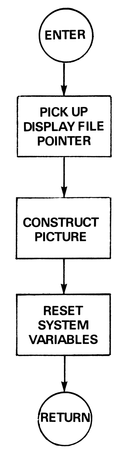
Pick up Display File pointer: The Display file pointer is held as System Variables, 16396 & 16397, so this part the program is very straightforward. The HL register pair is loaded with the contents of locations 16396 & 16397, and then incremented to point to the location required for the starting character of the first line.
Assembler language     Decimal machine code
LD HL, (D-FILE)        42, 12, 64
INC HL                 35
Construct picture: Following the example of the BASIC program that drew a simple rectangle, a machine code routine must be written to draw a similar rectangle. End of line delimiting “118’s must be added as required. The following algorithm is just one solution of many, and it has been chosen as it closely copies the Basic program. It is not a very efficent algorithm but it is fairly easy to follow.
N.B. The decimal machine code instruction “118” has purposely been avoided, as the ZX80 will interpret it as an end of line delimiter if the machine code is stored in a REM statement. (see Chart 1)
Chart 1
Top     LD B, #32       6,32     (32 characters/row)
Edge    LD (HL), #9     54,9     (the shifted A)
        INC HL          35       (move to next character)
        DJNZ, EDGE      16,251   (loop until row finished)
        LD A, #117      62,117   (the top row delimiter)
        INC A           60       (117 + 1 = 118)
        LD (HL), A      119      (enter delimiter)
        INC HL          35       (move to next character)
Rows    LD B, #10       6, 10    (there are 10 rows)
Line    PUSH BC         197      (save the row number)
        LD (HL), #9     54, 9    (the shifted A)
        INC HL          35       (move to next character)
        LD B, #30       6, 30    (30 spaces/row)
Space   LD (HL), #0     54, 0    (enter a 'space')
        INC HL          35       (move to next character)
        DJNZ, Space     16, 251  (loop for 30 spaces)
        LD (HL), #9     54, 9    (the shifted A)
        INC HL          35       (move to next character)
        LD A, #117      62, 117  (a row delimiter)
        INC A           60       (117 + 1 = 118)
        LD (HL), A      119      (enter delimiter)
        INC HL          35       (move to next character)
        POP BC          193      (collect row number)
        DJNZ, Line      16, 234  (loop for 10 rows)
B-Line  LD B, #32       6, 32    (32 characters/row)
Edge-2  LD (HL), #9     54, 9    (the shifted A)
        INC HL          35       (move to next character)
        DJNZ, Edge-2    16, 251  (loop until row finished)
        LD A, #117      62, 117  (a row delimiter)
        INC A           60       (117 + 1 = 118)
        LD (HL), A      119      (enter delimiter)
        INC HL          35       (move to next character)
Reset System Variables: There are three system variables that require to be reset after any picture.
The DF-EA and the DF-END need to be filled with the address of the first free location in the Display File, i.e. the current contents of the HL register pair, and the line counter at 16421 must be filled with the value required. (The row counter at 16420 may also need to be reset, but this is not required in the present example.)
System  LD (DF-EA), HL              34, 14, 64
        LD (DF-END), HL             34, 16, 64
        LD A, #11                   62, 11       (rows unused)
        LD (LINE COUNTER), A        50, 37, 64
        RETURN                      201
Entering The Machine Code Routine: The above machine code routine has 64 instructions and all these instructions must be loaded into the RAM before the routine can be called. There are many ways in which machine code routines can be stored in the ZX80 but the method used below prevents the routine from being overwritten. However never try to LIST the whole program. (well, try it. After you have SAVED it)
Now enter the following program.
Machine code loader program:
10 REM    64 locations   (do not use spaces!)
20 LET CHECKSUM = 0
30 FOR I = 16427 TO 16490
40 INPUT A
50 LET CHECKSUM = CHECKSUM + A
60 POKE I, A
70 PRINT PEEK (I),
80 NEXT I
90 PRINT "CHECKSUM = "; CHECKSUM
The following lines also need to be entered and afterwards deleted (line number and Newline) so as to scroll line 10 off the screen.
100 PRINT  }
101 PRINT  }
102 PRINT  }
103 PRINT  }
104 PRINT  }   11 Dummy Lines
105 PRINT  }   (or more if the above
106 PRINT  }   program was changed)
107 PRINT  }
108 PRINT  }
109 PRINT  }
110 PRINT  }
SAVEing the program at this stage is advisable.
Now the Loader Program is ready to be RUN, so enter RUN and NEWLINE.
Enter the decimalised machine code instructions carefully. The values are repeated below in the format that appears on the screen. A CHECKSUM is incorporated for convenience. If a code has been entered wrongly, the correct value can either be entered directly using a POKE command, or the whole of the Loader can be RUN again.
Screen Display:
42      12      64      35
6       32      54      9
35      16      251     62
117     60      119     35
6       10      197     54
9       35      6       30
54      0       35      16
251     54      9       35
62      117     60      119
35      193     16      234
6       32      54      9
35      16      251     62
117     60      119     35
34      14      64      34
16      64      62      11
50      37      64      201
CHECKSUM = 4033
Once the machine code has been entered correctly, SAVE the program again. Now comes the moment of truth! Enter a line containing USR(16427). e.g. LET K=USR(16427) and the rectangle should appear.
If the rectangle does not appear go back to one of the SAVEd versions and find the error.
The best form in which to save the routine is to delete lines 30-90, and to replace line 20 with:
20 REM LINE 10 IS OFF THE SCREEN,
USE LET K=USR(16427) TO DRAW A
RECTANGLE.
So now SAVE the final version.
A Demonstration Program
The following extract from a mixed BASIC/Machine code Life program for the ZX80 shows the above routine at work.
10 REM (prepared as above and held off
the screen)
20 LET A = USR (16427)
30 INPUT A
40 IF A [illegible] 1 OR A [illegible] 300 THEN GO TO 30
50 LET A=PEEK(16396)+PEEK(16397)
*256+34+A+((A-1)/30)*3
60 POKE A, -52*(PEEK(A)=0)
70 GO TO 30
The above program is used to enter characters into the required positions. The program also contains the facility of removing a character by overwriting the character with a “space”.
I hope that the above article will prove useful to many readers, and I would certainly be interested in seeing any programs written as a direct result of reading this article.
Note: Type-in program listings on this website use ZMAKEBAS notation for graphics characters.