I recently purchased some Spectrum ROMs from Zebra Systems with the hope that I might be able to make my own Spectrum ROM switching circuit without paying the high price of those circuits that are commercially available. When I examined the TS-2068’s ROM circuitry, I realized that this.was an easier task than I had originally assumed! All that I needed was: a Spectrum ROM, an SPDT toggle switch (Radio Shack #275-6725), two feet of insulated wire and two 10K ohm resistors (Radio Shack #271-133)
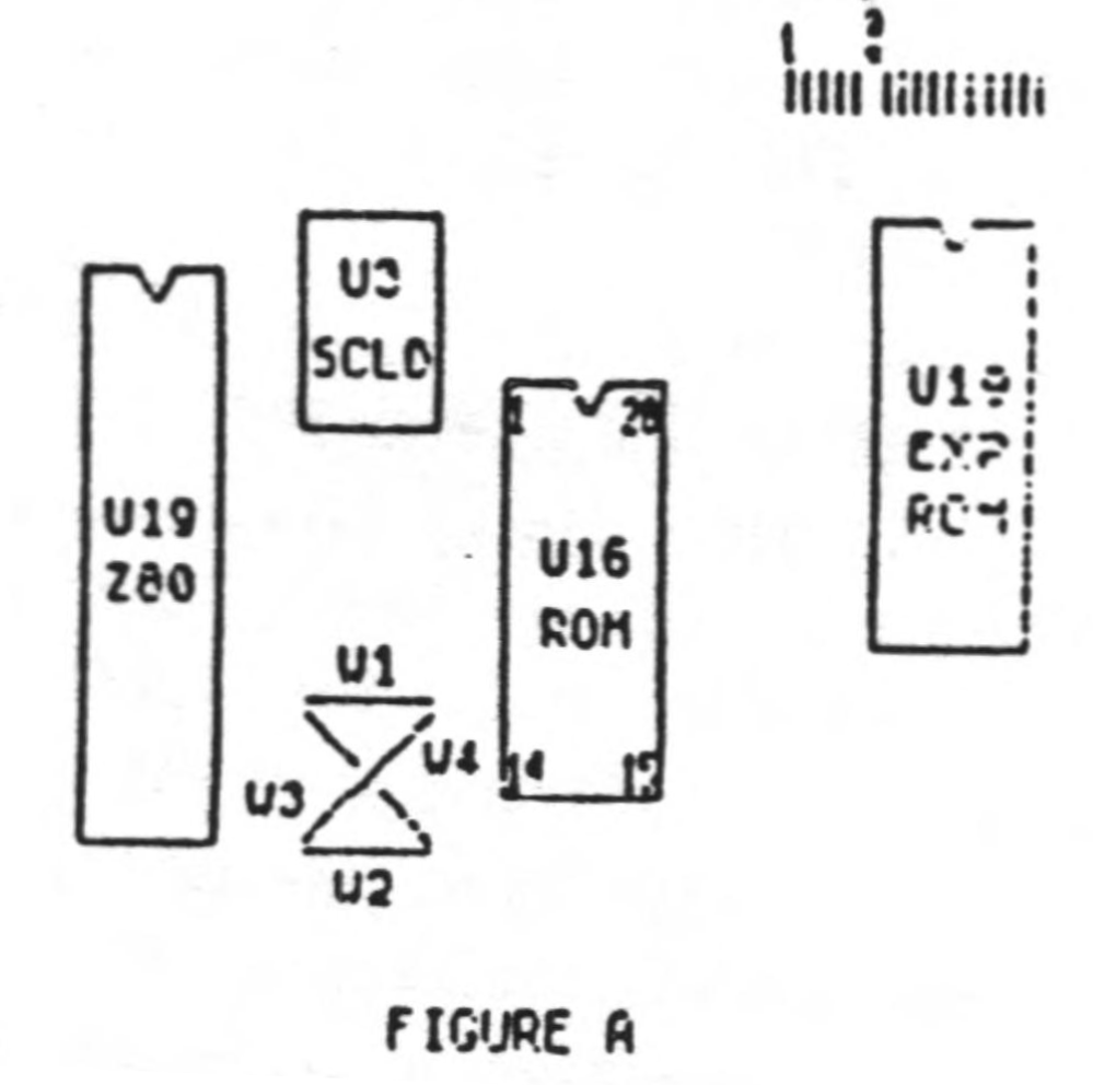
To start the project, you first remove the top from your computer case by removing the seven screws in the bottom of the case. When you look inside. it will appear as in figure 1. You now remove the Timex ROM (U16). To remove it, gently pry it with a small screwdriver or knife inserted between the socket and the ROM. It is Important that you test your Spectrum ROM before constructing this circuit. To test it, place it in the socket from which you have removed the TS-2068 ROM and energize your computer. The Sinclair copyright should be displayed. If not, your ROM may be defective. After the test, remove the Spectrum ROM.
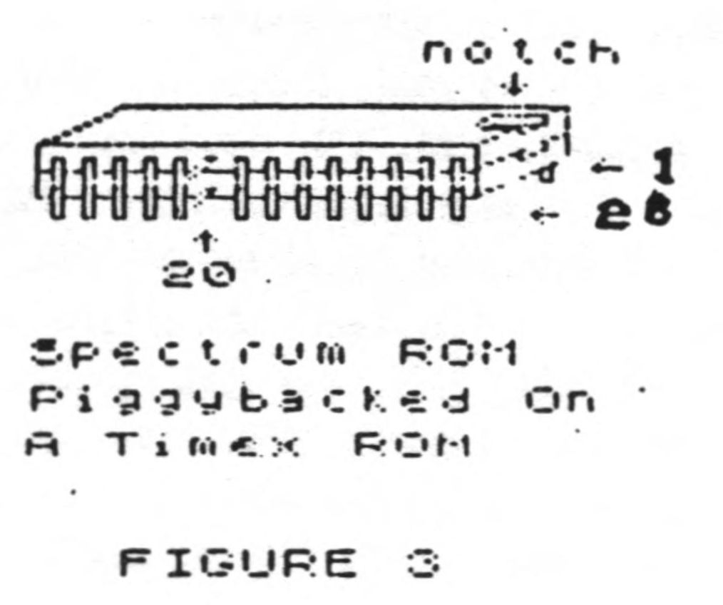
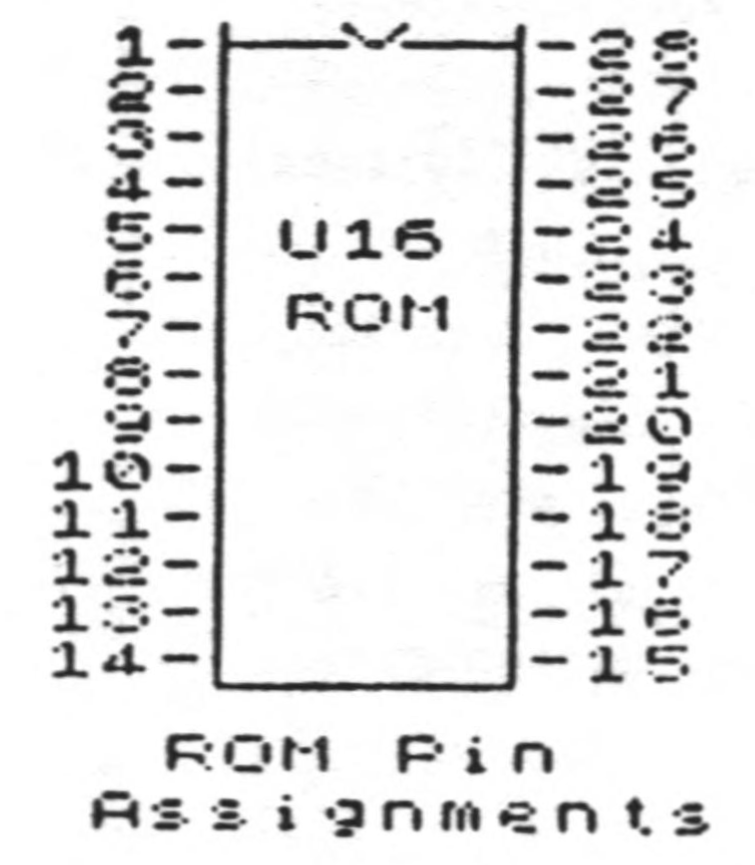
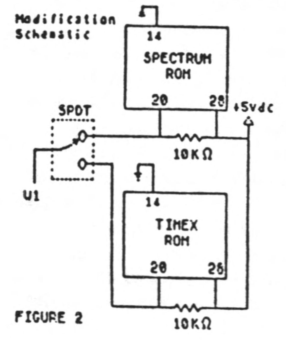
Take your Timex ROM and place your Spectrum ROM directly over it with the notches in the same direction (see figure 3). There should only be a thin space between the two ROMs and all of their leads should be touching. Do not leave a lot of space between these ROMs because clearance is critical when you because reassemble you computer! You will now, very gently, bend pin 20 on both ROMs upward until they are perpendicular to the other pins. You may now solder all of the pins except pin 20. Be careful when soldering. Allow 30 seconds between the soldering of each pin so that you won’t overheat and danage the ROMs. To pin 20 of each ROM, you will solder a peice of wire and one end of a 10K ohm resistor. The other end of each 10K ohm resistor will be soldered to pin 28 (+5vdc). The other end of the two wires that you have coming from pin 20 of the two ROMs will be soldered to the toggle switch. The toggle switch has three pins on it. Two of these pins are labled “ON”. Solder one wire to each of these two pins. Another wire w111 be soldered to the middle pin of the the toggle switch with the other end of that wire going to the circuit board and soldered to W1.
Image Gallery